Do-it-yourself gyroplane: drawings, description. Homemade gyroplanes
How to make a gyroplane with your own hands? This question was most likely asked by those people who really love or want to fly. It is worth noting that perhaps not everyone has heard of this device, since it is not very common. They were widely used only until helicopters were invented in the form in which they exist now. From the moment such aircraft models took to the skies, gyroplanes immediately lost their relevance.
How to build a gyroplane with your own hands? Drawings
Creating such an aircraft will not be difficult for anyone who is interested in technical creativity. Special tools or expensive ones building materials won't be needed either. The space that will have to be allocated for assembly is minimal. It’s worth adding right away that assembling a gyroplane with your own hands will save a huge amount of money, since buying a factory model will require huge financial costs. Before you begin the process of modeling this device, you need to make sure you have all the tools and materials at hand. The second step is the creation of a drawing, without which it is not possible to assemble a standing structure.
Basic design
It’s worth saying right away that building a gyroplane with your own hands is quite simple if it’s a glider. With other models it will be somewhat more difficult.
So, to start work you will need to have three duralumin power elements among the materials. One of them will serve as the keel of the structure, the second will act as an axial beam, and the third will serve as a mast. You can immediately attach a steerable nose wheel to the keel beam, which must be equipped with braking device. The ends of the axial force element must also be equipped with wheels. You can use small parts from a scooter. Important point: if you assemble a gyroplane with your own hands for flying behind a boat in tow, then the wheels are replaced with controlled floats.

Farm installation
Another main element is the farm. This part is also mounted on the front end of the keel beam. This device is a triangular structure, which is riveted from three duralumin corners, and then reinforced with sheet overlays. The purpose of this design is to secure the towbar. The construction of a do-it-yourself gyroplane with a truss must be made in such a way that the pilot, by pulling the cord, can unhook from the tow rope at any time. In addition, the truss is also necessary so that the simplest air navigation instruments can be installed on it. These include a flight speed tracking device, as well as a lateral drift mechanism.

Another main element is the installation of the pedal assembly, which is installed directly under the truss. This part must have a cable connection to the aircraft control rudder.
Frame for the unit
When assembling a gyroplane with your own hands, it is very important to pay due attention to its frame.
As mentioned earlier, this will require three duralumin pipes. These parts should have a cross-section of 50x50 mm, and the thickness of the pipe walls should be 3 mm. Similar elements are often used when installing windows or doors. Since it will be necessary to drill holes in these pipes, you must remember important rule: when carrying out work, the drill should not damage the inner wall of the element, it should only touch it and no more. If we talk about choosing a diameter, then it should be selected so that the MB type bolt can fit as tightly as possible into the resulting hole.

One more important note. When drawing up a drawing of a gyroplane with your own hands, you need to take into account one nuance. When assembling the apparatus, the mast should be tilted back slightly. The angle of inclination of this part is approximately 9 degrees. When drawing up a drawing, this point must be taken into account so as not to forget later. The main purpose of this action is to create an angle of attack of the gyroplane blades of 9 degrees even when it is just standing on the ground.
Assembly
Assembling the gyroplane frame with your own hands continues with the need to secure the axial beam. It is attached to the keel across. To securely fasten one base element to another, you need to use 4 MB bolts, and also add locked nuts to them. In addition to this fastening, it is necessary to create additional rigidity of the structure. To do this, use four braces that connect the two parts. The braces must be made of angle steel. At the ends of the axle beam, as mentioned earlier, it is necessary to secure the wheel axles. To do this, you can use paired clips.

The next step in assembling a gyroplane with your own hands is to make the frame and seat back. In order to collect this small design, it is best to also use duralumin pipes. Parts from children's cots or strollers are great for assembling the frame. To fasten the seat frame at the front, two duralumin corners with dimensions of 25x25 mm are used, and at the back it is attached to the mast using a bracket made of a steel corner 30x30 mm.
Checking the gyroplane
After the frame is ready, the seat is assembled and attached, the truss is ready, navigation devices and other equipment are installed important elements gyroplane, you need to check how it works finished design. This must be done before the rotor is installed and designed. Important Note: It is necessary to check the performance of the aircraft at the site from which further flights are planned.
Most people who are not directly involved in aviation, seeing this aircraft in flight or standing on the ground, will most likely think: “ What a cute little helicopter!- and immediately make a mistake. In fact, it all ends with external similarity. The fact is that for the flight of a gyroplane and a helicopter, completely different principles are used.
Why does a gyroplane fly?
At the helicopter lifting and driving force created by rotating the main rotor(one or more), a permanent drive to which is transmitted from the engine through a complex transmission system. The swashplate changes the plane of the rotating screw in in the right direction, providing forward movement and maneuvering, adjusting speed.
A story about another type of ultralight aircraft - also read on our website.
The story about a motorized paraglider and an aerochute is located. Find out what devices there are with soft wing and thrust on the engine.
 The design and principle of operation of a gyroplane is completely different, and probably even more similar to an airplane (glider, trike).
The lifting force is provided by the oncoming air flow, but a freely rotating propeller acts as a wing(it is usually called a rotor). The forward movement is provided by the pulling or pushing force of the main engine, located, respectively, in front or behind the aircraft. And what gives the rotor rotation is just the oncoming air flow. This phenomenon is called autorotation.
Without a doubt, the principle was suggested by nature itself. You can pay attention to the seeds of some trees (maple, linden), which are equipped with a kind of propeller. Having matured, dried and separated from the branch, they do not fall vertically down. Air resistance spins their “rotors”, and the seeds can be quite long time plan, flying away from the native tree to very considerable distances. Gravity, of course, takes its toll, and their landing is inevitable. But this is the task of human genius: to find means to control such a flight.
In a gyroplane, power is taken from the engine to the rotor only in the very initial phase of flight, in order to give it the rotation speed necessary for takeoff. Next - a short run-up, ascent - and that's it, the law of autorotation comes into force - the rotor rotates completely independently, until the device lands completely. Located at a certain angle of attack, it creates the lift necessary for flight.
History of the aircraft
The first person to seriously engage in research and practical application of the principle of autorotation was the Spanish design engineer Juan de la Cierva. Having begun to engage in aircraft construction at the very dawn of aviation, he had to survive the disaster of his brainchild - a three-engine biplane, and he completely switched to a completely unexplored branch of aeronautics.
After lengthy tests in a wind tunnel, he also formulated and theoretically substantiated the principle of autorotation. By 1919, the first model had been developed in drawings, and in 1923, the S-4 gyroplane took off for the first time. By design, it was a regular aircraft body, equipped with a rotor instead of wings. After a number of modifications, a small serial production of similar devices was even launched in France, England, and the USA.
 Soviet aircraft designers followed an almost parallel course. In a specially created department special designs(OOK) TsAGI was developing its own gyroplanes. In the end the first Soviet device KASKR-1 took off in 1929.
It was developed by a group of young engineers, which included Nikolai Ilyich Kamov, Later - outstanding aircraft designer helicopters of the Ka series. It is noteworthy that Kamov, as a rule, always took part in the flight tests of his brainchild.
KASKR-2 was already more polished and reliable car, which was demonstrated to a representative government commission at Khodynka airfield in May 1931.
Further research and design improvements led to the creation of a production model, which was called R-7. This device was created according to the design of a winged gyroplane, which made it possible to significantly reduce the load on the rotor and increase speed characteristics.
N.I. Kamov not only developed and improved his apparatus, but also constantly looked for it practical application. Already in those years, R-7 gyroplanes carried out pollination of agricultural land.
During the rescue operation to remove Papanin’s first polar expedition from the ice floe in 1938, the Ermak icebreaker had an R-7 ready for takeoff. Although the help of such carrier-based aircraft was not needed then, the fact itself speaks of the high reliability of the vehicle.
Unfortunately, Second World War interrupted many design initiatives in this area. The subsequent craze for helicopter technology pushed gyroplanes into the background.
The gyroplane is at war
 It is clear that in the first half of the last century, during this extremely militarized period, any new developments were considered in terms of their use for military needs. The gyroplane did not escape this fate either.
The first combat rotorcraft was the same R-7. Given its ability to lift a payload of 750 kg into the air, it was equipped with 3 machine guns, photographic equipment, communications equipment and even a small bomb kit.
Combat squadron of gyroplanes A-7-ZA consisting of 5 units took part in the battles on the Elninsky ledge. Unfortunately, the enemy’s complete dominance in the sky at that time did not make it possible to use these low-speed vehicles for actual reconnaissance during the day - they were used only at night, mainly for scattering propaganda materials over enemy positions. It is significant that the squadron engineer was none other than M.L. miles, future designer Mi series helicopters.
Our opponents also used gyroplanes. A non-motorized vehicle was developed specifically for the needs of the German submarine fleet. Focke-Achgelis FA-330, essentially a kite gyroplane. It was assembled in a matter of minutes, then the rotor was forcibly spun, and the gyroplane took off to a height of up to 220 meters, towed by a submarine moving at full speed. This flight altitude allowed observation within a radius of up to 50 kilometers.
The British also made bold attempts. In preparation for the upcoming invasion of Northern France, they generally planned to combine a gyroplane with an army combat jeep for landing from a heavy bomber. True, even after fairly successful tests, the issue was dropped.
Advantages and disadvantages of a gyroplane
 The creators of the gyroplane managed to solve a lot of safety and flight efficiency issues that cannot be implemented on airplanes or helicopters:
- Loss of speed, for example, when the main engine fails, does not lead to stalling in a “tailspin.”
- Autorotation of the rotor allows you to perform soft landing even with complete loss of translational motion. By the way, this property is also used in helicopters - they provide for the inclusion of an autorotation mode in emergency situations.
- Short takeoff run and landing area.
- Insensitive to thermal flows and turbulence.
- It is economical to operate, easy to build, and its production is much cheaper.
- Controlling a gyroplane is much easier than that of airplanes or helicopters.
- It is practically not afraid of wind: 20 meters per second is normal conditions for it.
There are, of course, a number shortcomings, which enthusiastic designers are constantly working to eliminate:
- There is a possibility of somersault during landing, especially for models with a weak tail.
- The phenomenon called the “dead zone of autorotation”, which leads to the cessation of rotation of the rotor, has not been fully studied.
- Flights on a gyroplane in conditions of possible icing are unacceptable - this can lead to the rotor leaving the autorotation mode.
In general, the advantages far outweigh the disadvantages, which allows us to classify the gyroplane as the safest aircraft.
Is there a future?
 Fans of this type of mini-aviation unanimously answer such a question that the “era of gyroplanes” is just beginning. Interest in them has revived with renewed vigor, and now serial models of such aircraft are being produced in many countries around the world.
In terms of capacity, speed and even fuel consumption, the gyroplane boldly competes with conventional passenger cars, surpassing them in its versatility and not being tied to roads.
In addition to the purely transportation function, gyroplanes find their application in carrying out tasks of patrolling forests, sea coasts, mountains, and busy highways; they may well be used for aerial photography, video recording or surveillance.
Some modern models are equipped with a “jumping” take-off mechanism, others allow a successful take-off from a standstill in the presence of winds of more than 8 km/h, which further increases the functionality of gyroplanes.
The leading manufacturer of such devices on the modern market is a German company Autogyro, producing up to 300 cars per year. The Russians are also trying to keep up - in our country they produce a number of serial models: “Irkut” of the Irkutsk Aviation Plant, “Twist” of the Twister Club flying club, “Hunter” of the Aero-Astra Scientific and Production Center and others.
The number of fans of this type of sky conquest is constantly growing.
Photo gallery of gyroplanes


IN recent years Aviation enthusiasts from many countries show great interest in flying homemade gyroplanes and gyroplanes themselves. Inexpensive, easy to manufacture and easy to pilot, these aircraft can be used not only for sports, but also as an excellent means of introducing wide circles of young people to air element. Finally, they can be successfully used for communication. In the 1920s – 1940s, gyroplanes were built in many countries. Now they can only be seen in museums: they could not withstand the competition with helicopters. However, for sporting purposes, gyroplanes and especially towed gyroplanes are still used today (see figure).
In our country, the design and construction of microgyroplanes is mainly carried out by student design bureaus of aviation universities. The best cars this class was exhibited at exhibitions of technical creativity of youth, etc. Readers of “Modelist-Constructor” ask in numerous letters to tell us about the design of gliders-gyroplanes and micro-gyroplanes. This issue was at one time quite well covered on the pages of the magazine by master of sports G.S. Malinovsky, who even in the pre-war years took part in experimental work with industrial-built gyroplanes.
Essentially, this article is still relevant because it touches on an interesting area of technical creativity where aviation enthusiasts can and should achieve great success. The article does not at all claim to be an exhaustive coverage of the issue. This is just the beginning of a big conversation.
THE CONVERSATION STARTS WITH A “FLY”
Everyone knows the flying toy known as the Fly. This is a main rotor (propeller) mounted on a thin stick. As soon as you spin the stick with your palms, the toy itself breaks out of your hands and quickly flies up, and then, smoothly rotating, falls to the ground. Let's understand the nature of its flight. “Mukha” took off because we spent a certain amount of energy on its promotion - it was a helicopter (Fig. 1).


Now let’s tie a 3-5 m long thread to the stick on which the rotor is mounted and try to pull the “Fly” against the wind. She will take off and favorable conditions, spinning quickly, will gain altitude.
This principle is also inherent in the gyroplane: during the take-off run along the runway, its main rotor, under the influence of the oncoming flow, begins to unwind and gradually develops a lifting force sufficient for take-off. Consequently, the main rotor - the rotor - performs the same role as the aircraft wing. But, compared to a wing, it has a significant advantage: its forward speed with equal lifting force can be much less. Thanks to this, the gyroplane is able to descend almost vertically in the air and land on small areas (Fig. 2). If, during takeoff, you spin the rotor blades at a zero angle of attack, and then sharply move them to a positive angle, then the gyroplane will be able to take off vertically.

WHAT DID J. BENSEN FLY ON?
The prototype of most amateur gliders-gyroplanes was the car of the American I. Bensen. It was created shortly after the end of World War II and aroused great interest in many countries. According to official data, over several thousand devices of this kind have currently been built and are successfully flying.
The gyroplane of I. Bensen consists of a cross-shaped metal frame A, on which a pylon B is rigidly mounted, serving as a support for the rotor B with a direct control lever G. In front of the pylon there is a pilot’s seat D, and on the back of the frame there is a simple vertical tail, consisting of a keel E and a rudder direction G. The latter is connected by cables to a foot pedal located in the front part of the frame. The gyroplane chassis is three-wheeled, with lightweight pneumatic tires (the side wheels have a size of 300×100 mm, the front, steering wheel – 200×75 mm). Under the rear part of the frame there is an additional support wheel made of hard rubber with a diameter of 80 mm. The rotor has a metal hub and two wooden blades describing a circle with a diameter of 6 m. The chord of the blade is 175 mm, the relative thickness of the profile is 11%, the material is high-quality wood, glued with plywood and reinforced with fiberglass. Flights of the Bensen glider-gyroplane were carried out in tow behind a car (Fig. 5). Subsequently, a 70-horsepower engine with a pusher propeller was installed on similar machines.


Polish designers Alexander Bobik, Czeslaw Yurka and Andrei Sokalsky created a glider-gyroplane (Fig. 4) that takes off from the water. It was towed by a speedboat or motorboat with a powerful outboard motor (about 50 hp). The glider is mounted on a float, similar in shape and design to the body of a sports scooter junior classes. The directly controlled rotor is mounted on a simple and lightweight pylon, braced with cable braces to the float body. This made it possible to achieve a minimum weight of the structure with sufficient reliability. The technical data of the glider-gyroplane, which its authors called the “viroglider”, are as follows: length - 2.6 m, width - 1.1 m, height -1.7 m, total weight structure - 42 kg, rotor diameter - 6 m. Its flight data: take-off speed - 35 - 37 km/h, maximum permissible - 60 km/h, landing - 15 - 18 km/h, rotor speed - 300 - 400 rpm
Polish designers made many successful flights on their “viroglider”. They believe that their car has a great future. One of the creators of the “viroglider”, Cheslav Yurka, wrote: “Subject to the elementary rules of caution, high discipline of the boat driver and service personnel flights on “virogliders” are completely safe. Large quantity lakes, the water surface of which is always free, will allow everyone to engage in this exciting sport and recreation.”
CONTROL SYSTEM
Let's figure out how the car's controllability is ensured. On an airplane it is simple - there are elevators, a rudder and ailerons. By deflecting them in the right direction, any evolutions are carried out. But rotorcraft, it turns out, do not need such rudders: a change in flight direction occurs immediately as soon as the rotor axis changes its position in space. To change the inclination of the rotor axis on the glider-gyroplane, a device consisting of two bearings is used; fixedly fixed in the cheeks of head A and connected to control lever B. Bearing A, being spherical, allows the rotor shaft to deviate from the main position by 12° in any direction, which provides the machine with longitudinal and lateral controllability.
The rotor control lever, rigidly connected to the lower bearing housing, has a crossbar resembling a bicycle handlebar, which the pilot holds with both hands. For takeoff, to move the rotor to a large angle, the lever moves forward; to reduce the angle and move the machine into horizontal flight - backwards; to create a roll to the right (or eliminate a left roll), the lever is deflected to the left; with a right roll - to the right. This feature of controlling gyroplanes creates certain difficulties for pilots flying conventional gliders, airplanes and helicopters (the handle movements of all these machines are directly opposite in sign).
Therefore, before flying on gyroplanes with direct control, it is necessary to undergo special training on a simulator. You can, however, go for some complication of the design by equipping the machine with “normal” aircraft-type controls (shown by the dotted line on the diagram of the Bensen gyroplane, see Fig. 3),
BEFORE YOU BUILD
A glider-gyroplane has significantly fewer parts than a regular bicycle. But this does not mean that it can be made somehow, tying it with wire in one place, and inserting a nail instead of a bolt in another.
All parts must be manufactured, as they say, at the highest aviation level: after all, human life depends on their quality and reliability. Even if you fly over water. Therefore, we must immediately make the following decision: if it is possible to complete all the work with high quality, we will build a viroglider; if not, we will postpone construction until better times.


The most important and difficult part in the manufacture of a viroglider is, of course, the rotor. Attempts to use used blades from helicopters produced by our industry for installation on homemade gyroplanes were not successful, since they are designed for other modes. Therefore, they should not be used under any circumstances. Typical design The blade is shown in Figure 6. To glue the spar, you need to prepare straight-layer, well-dried pine slats and carefully joint them together. They are collected in a package, as shown in Figure 7. Strips of ASTT6 grade fiberglass, pre-coated with epoxy glue, must be placed in the spaces between the slats. The slats should also be coated on both sides. After the necessary exposure, the package is pressed into a device that ensures straightness of the product along both the wide and narrow sides of the package. After drying, the package is processed in accordance with a given profile, forming the front part (“nose”) of the blade. The processing must be done very carefully, using steel counter-templates. The “tail” of the blade is made of polystyrene foam blocks of PCV-1 or PS-2 grade, reinforced with a number of plywood ribs. Gluing should be done in a special slipway (Fig. 8) to ensure the correct profile. The final processing of the blade is carried out with a file and sandpaper, using counter-templates, after which the entire blade is covered with thin fiberglass cloth on epoxy glue, sanded, painted bright color and is polished first with pastes and then with polishing water.
The finished blade, placed at its ends on two supports, must withstand at least 100 kg of static load.
To connect to the rotor hub, steel plates are secured on each blade with six M6 bolts, as shown in the drawing; in turn, these plates are attached to the hub with two M10 bolts. Trimmer D and counterweight G are installed on a fully finished blade. The weight is on three M5 bolts, the trimmer is on five rivets with a diameter of 4 mm. A wooden boss is glued in advance between the plywood ribs into the “shank” of the blade for riveting the trimmer.
The spherical bearing of the rotor head on foreign designs is selected ranging from a diameter of 50x16x26 mm to a diameter of 52x25x18 mm; Among domestic bearings of this type, No. 126 GOST 5720-51 can be used. In the diagram (Fig. 4) this bearing is shown as a single-row bearing for clarity. Lower control bearing – No. 6104 GOST 831-54.


A – base; B – hook; B – installation of the lock on the glider-gyroplane (hook down); D – installation of the lock on the towing boat (hook up)


Extreme simplicity of design - characteristic feature gyroplanes I. Bensen

The control lever can be secured to the bearing housing with brackets, as shown in Figure 4 (this allows the entire assembly to be disassembled into individual elements), or welding.
The base (“heel”) of the pylon is attached in the float body to a stiffening rib connected by four M6 bolts to the keel. These bolts simultaneously secure the outer metal feather to the float body. It is advisable to tighten the guy ropes connecting the pylon with the sides of the float before braiding with a force of 150 - 200 kg. Thunderbolts are aircraft grade, with threaded rods 5 mm thick.
As mentioned above, the weight of the viroglider must be kept within the range of 42 – 45 kg. It's not as simple as it seems at first glance. You need to choose very carefully necessary materials, handle and assemble correctly, do not use heavy putties and paints. This is especially true for the manufacture of a float. His wooden frame should be assembled from well-dried slats of straight-grained, light (not resinous) pine. The best wood for making a float frame is the so-called “aviation” pine in fire monitors, but it is not available everywhere and cannot always be obtained. Therefore, one should not neglect possible substitutes: for example, a good container board or slats sawn from a thick slab (slab is the sapwood, the strongest part of the trunk; when properly sawed, it produces excellent slats of the desired section). Quite often, canned food is packed in good boxes. Having collected two or three dozen of these container boards, you can choose from them what you need for your work. Each rail must be tested for strength before being installed in place. If it breaks, it doesn’t matter, you can install another one; but you will have full confidence that the set is made of reliable material.
G. MALINOVSKY
This time, friends and comrades, I propose to move to a different element of vehicles - air.
Despite the all-encompassing hell and destruction on earth, you and I do not lose hope and dream of conquering heaven. And a relatively inexpensive means for this will be a miracle stroller with a propeller, whose name is gyroplane.

Autogyro(autogyro) - a rotary-wing ultra-light aircraft, in flight resting on the bearing surface of a rotor rotating freely in autorotation mode.
This thing is otherwise called Gyroplane(gyroplane), Gyrocopter(gyrocopter), and sometimes Rotoglider(rotaplane).
A little history
Autogyros were invented by Spanish engineer Juan de la Cierva in 1919. He, like many aircraft designers of that time, tried to create a flying helicopter and, as is usually the case, he created it, but not what he originally wanted. But he was not particularly upset about this fact and in 1923 he launched his personal apparatus, which flew due to the autorotation effect. Then he started his own company and slowly riveted his own gyrocopters until he died. And then a full-fledged helicopter was designed, and interest in gyroplanes disappeared. Although they continued to be produced all this time, they were (and are) used for narrow purposes (meteorology, aerial photography, etc.).


Specifications
Weight: from 200 to 800 kg
Speed: up to 180 km/h
Fuel consumption: ~15 l per 100 km
Flight range: from 300 to 800 km

Design


By design, the gyroplane is closest to helicopters. In fact, it is a helicopter, only with an extremely simplified design.

The design itself includes the following key elements: load-bearing structure- the “skeleton” of the vehicle to which the engine is attached, 2 propellers, a pilot’s seat, control and navigation instruments, tail unit, landing gear and some other elements.
Direct control is carried out by two pedals and a control lever.

The simplest gyrocopters require a short run of 10 to 50 meters to take off. This distance decreases depending on the increase in the strength of the headwind and the degree of rotation of the main rotor at the start of the takeoff run.
A special feature of a gyroplane is that it flies as long as there is an air flow flowing onto the main rotor. This flow is provided by a small pusher screw. It is for this gyroplane that at least a short run is needed.
However, more complex and expensive gyroplanes, equipped with a mechanism for changing the angle of attack of the blade, are capable of taking off from a place vertically upward (the so-called jump).
Changing the position of the gyroplane in the horizontal plane is achieved by changing the angle of inclination of the entire plane of the rotor.
A gyroplane, just like a helicopter, can hover in the air.
If the engine of a gyroplane fails, this does not mean the certain death of the pilot. If the engine is turned off, the gyroplane rotor goes into autorotation mode, i.e. continues to rotate from the oncoming air flow while the device moves at a downward speed. As a result, the gyroplane slowly descends rather than falling like a stone.

Varieties
Despite the simplicity of their design, gyrocopters have some design variability.
Firstly, these aircraft can be equipped with either a pulling or pushing propeller. The first are characteristic of historically the very first models. Their second propeller is located at the front, like some airplanes.
The second ones have a screw at the back of the device. Gyroplanes with a pusher propeller are the vast majority, although both designs have their advantages.

Secondly, although a gyroplane is a very light air vehicle, it can carry a couple more passengers. Naturally, there must be appropriate design capabilities for this. There are gyroplanes with the ability to transport up to 3 people, including the pilot.
![]()

Thirdly, the gyroplane may have a fully enclosed cabin for the pilot and passengers, a partially enclosed one, or may not have a cabin at all, which is retracted for the purposes of carrying capacity or better visibility.

Fourthly, it can be equipped with additional niceties, such as a swashplate and so on.

Combat use
The effectiveness of the gyroplane as a strike weapon is of course low, but it managed to be in service with the SA for some time. In particular, at the beginning of the 20th century, when the whole world was gripped by helicopter fever, the military observed developments in this industry. When full-fledged helicopters did not yet exist, there were attempts to use the gyrocopter for military purposes. The first gyrocopter in the USSR was developed in 1929 under the name KASKR-1. Then, over the next ten years, several more models of gyroplanes were released, incl. gyroplanes A-4 and A-7. The latter took part in the war with the Finns as a reconnaissance aircraft, night bomber and tow truck. Although there were certain advantages in using a gyroplane, all this time the military leadership doubted its necessity and serial production The A-7 was never delivered. Then the war began in 1941 and there was no time for that. After the war, all efforts were devoted to creating a real helicopter, but they forgot about the gyroplane.

The Soviet A-7 gyroplane was armed with 7.62 PV-1 and DA-2 machine guns. It was also possible to attach FAB-100 bombs (4 pcs.) and RS-82 unguided rockets (6 pcs.)

The history of the use of gyroplanes in other countries is approximately the same - the devices were used at the beginning of the 20th century by the French, British, and Japanese, but when helicopters appeared, almost all gyroplanes were decommissioned.
Subject and PA
It’s probably clear why the subject of “PA Technique” was the gyroplane. It is very simple, light, maneuverable - with a certain straightness of hands it can be assembled at home (apparently this is where the stories about prisoners and the helicopter from the Druzhba chainsaw came from).

Despite all its advantages, we get good opportunity conquer airspace in very bad environmental conditions.

In addition to the banal movement by air and transportation of more or less cargo, we get a good combat unit that can be tactfully used in reconnaissance and patrol operations. Moreover, it is quite possible to install automatic weapons, as well as use live shells for bombing. As they say, the need for invention is cunning, if only there was a desire.

So, let's summarize. I divided the advantages of the subject into absolute and relative. Relative - in comparison with other aircraft, absolute - in comparison with vehicles in general, incl. and ground.
Absolute advantages
Ease of manufacture and repair
Easy to use
Easy to control
Compactness
Low fuel consumption
Relative Advantages
High maneuverability
Resistance to strong winds
Safety
Landing without a run
Low vibrations in flight
Flaws
Low load capacity
Low security
High sensitivity to icing
Quite a loud noise from the pusher propeller
Specific disadvantages (rotor unloading, somersault, autorotation dead zone, etc.)
YouTube about the subject
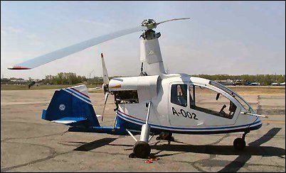
Lightweight autogyro DAS-2M.
Developer: V. Danilov, M. Anisimov, V. Smerchko
Country: USSR
First flight: 1987
For the first time, the DAS gyroplane took to the air in a non-motorized version, towed by a Zhiguli car. This happened at one of the agricultural aviation airfields near Tula. But it took more years, during which the designers worked on the engine, before the most experienced LII test pilot V.M. Semenov, after just one run, took the DAS-2M into the air. This event was later celebrated at SLA competitions with a special prize from the Mil Design Bureau. The device, according to the test pilot, has good flight characteristics and efficient control.
Design.
The fuselage is of a truss, tubular, collapsible design. The main element of the fuselage is a frame consisting of horizontal and vertical (pylon) pipes with a diameter of 75 x 1, made of 30KhGSA steel. Attached to them are a towing device with a lock and an air pressure receiver, an instrument panel, a pilot's seat equipped with a seat belt, a control device, a three-wheeled landing gear with a steerable nose wheel, a power unit mounted on a motor mount with a pusher propeller, a stabilizer, a keel with a rudder, a ball main rotor hinge. An auxiliary tail wheel with a diameter of 75 mm is installed under the keel. The pylon together with struts with a diameter of 38 x 2, a length of 1260 mm, tubular beams of the main wheels with a diameter of 42 x 2, a length of 770 mm, made of titanium alloy VT-2, and braces with a diameter of 25 x 1, a length of 730 mm made of 30KhGSA steel form a spatial load-bearing frame, in in the center of which the pilot is located. The pylon is connected to the horizontal fuselage tube and the main rotor ball joint using titanium gussets. In the area where the gussets are installed, bougies made of B95T1 duralumin are installed in the tubes.
The power unit is with a pusher propeller. It consists of a two-cylinder opposed two-stroke engine with a displacement of 700 cm3 with a gearbox, a pusher propeller and an electric starter, a friction clutch for a rotor pre-spin system, an 8-liter gas tank and electronic system ignition The power unit is located behind the pylon, on the motor frame.
The engine is equipped with a redundant electronic contactless ignition system and a tuned exhaust system.
The pushing wooden screw is driven by a V-belt gearbox, consisting of drive and driven pulleys and six belts. To reduce torque unevenness, dampers are installed on the gearbox.
The main rotor with a diameter of 6.60 m is two-bladed. The blades, consisting of a fiberglass spar, foam filling and covered with fiberglass, are mounted with one horizontal hinge on a bushing located on the pylon. At the ends of the blades there are uncontrolled trimmers for adjusting the cone of the main rotor. The driven gear of the pre-spin gear and the main rotor tachometer sensor are installed on the main rotor axis. The gearbox is driven using cardan-spline shafts, angular gearbox mounted on the pylon, and a friction clutch located on the engine. The friction clutch consists of a driven rubber roller mounted on the axis of the cardan-spline shaft, and a driving duralumin drum located on the engine axis. The friction clutch is controlled using a lever mounted on the control handle.
Changes in roll and pitch are carried out by a handle that affects the position of the lower control fork, connected by rods to the upper fork, which, in turn, leads to a change in the inclination of the rotor rotation plane.
Directional control is carried out by a rudder connected by cable wiring to pedals that control the nose wheel. To compensate for the hinge moment, the rudder is equipped with a horn-type compensator. The rudder and keel of a symmetrical profile are made of 16 plywood ribs 3 mm thick, pine stringers 5 x 5 mm, covered with percale and coated with nitro varnish. The keel is mounted on the horizontal fuselage tube using anchor bolts and two cable braces.
The gyroplane chassis is three-wheeled. The front steered wheel, measuring 300 x 80 mm, is connected to the pedals using a gear reducer with a gear ratio of 1:0.6 and is equipped with a parking brake drum type diameter 115 mm.
The instrument panel is located on the towing device truss. The instrument panel is equipped with a speed indicator, variometer, altimeter connected to an air pressure receiver, and tachometers for the main and pusher propellers. On the control handle there is a toggle switch for emergency engine stop and a friction clutch control handle. The control levers for the carburetor throttle valve and the device for forced disengagement of the gearbox gears of the pre-spin system are installed on the pilot's seat on the left. The ignition switch is located on the right. To the left of the instrument panel is the parking brake lever. All mechanisms of the gyroplane are driven using cables with Bowden sheaths.
Main rotor diameter, m: 6.60
Max. take-off weight, kgf: 280
Empty gyroplane weight, kgf: 180
Fuel weight, kgf: 7
Specific load, kgf/m2: 8.2
Power point,
-power, hp: 52
-Max. propeller speed, rpm: 2500
-screw diameter, m: 1.46
Speed, km/h,
-take-off: 40
-landing: 0
-cruising: 80
-maximum: 100
Rate of climb, m/s: 2.0.
Autogyro DAS-2M.
