Constructive solutions for modern brick walls. Structural solutions for buildings
The building wall is the main enclosing structure of the building. Along with enclosing functions, walls simultaneously, to one degree or another, also perform load-bearing functions (they serve as supports for absorbing vertical and horizontal loads).
The main requirements for walls: strength, heat resistance, sound insulation ability, fire resistance, durability, architectural expressiveness and economy.
There are external and internal walls. According to the nature of static work, external walls are divided into load-bearing walls, which, in addition to their own weight, perceive and transmit to the foundation loads from floors, coverings, wind pressure, etc.; self-supporting, resting on the foundation, bearing the load only from its own weight (within all floors of the building) and, to ensure stability, associated with the building frame: non-load-bearing (including hinged), accepting its own weight only within one floor and transferring it to frame or etc. support structures buildings. Internal walls can be load-bearing (major) or non-load-bearing (partitions are intended only to separate rooms, they are installed directly on the ceiling). In interior walls ah, they often arrange channels and niches for ventilation, gas ducts, water supply and sewer pipes etc. Load-bearing walls together with floors form a stable spatial system of the load-bearing frame of the building. In frame buildings, self-supporting walls often perform the functions of the so-called. rigidity diaphragms.
According to the method of construction, walls are divided into prefabricated, assembled from ready-made factory-made elements; monolithic - usually concrete, erected in movable or sliding formwork, hand-laid - from small-piece materials using mortars. Depending on the size of prefabricated elements, the degree of their factory readiness and the adopted cutting system, prefabricated walls are distinguished between large-block and large-panel. According to the constructive solution, the walls can be single-layer or multi-layer.
Materials for wall construction are selected depending on climatic conditions, purpose and capital of the building, its number of storeys, technical and economic feasibility. In multi-story construction of buildings with load-bearing walls, bricks, ceramic stones, large blocks of lightweight and cellular concrete, reinforced concrete panels and other large-sized products are used. Curtain walls, the weight of which should be minimal, are made of multilayer reinforced concrete panels with effective insulation, panels of extra-light concrete, asbestos-cement panels. In low-rise construction, wood, silicate and mud bricks, slag concrete, ceramic and natural stones are used.
The walls largely determine the design solution and the overall architectural appearance of the building. The name of the wall material often characterizes the architectural and structural type of the house: large-panel, large-block, brick, chopped wood, frame-panel, etc.
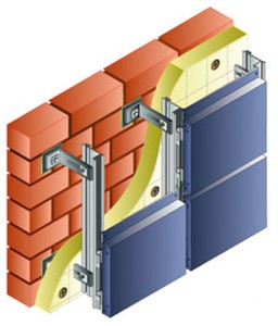
Load-bearing or self-supporting walls are a three-layer structure with a load-bearing layer of solid ceramic bricks thickness (250,380,510,640mm) as well as from concrete blocks or monolithic reinforced concrete with a layer of thermal insulation made of cast polystyrene foam.
The protective decorative layer can be made of thin-layer plaster 5-8 mm thick over an alkali-resistant fiberglass mesh or a ceramic wall solid brick 120mm thick.
IN wooden house building wall with effective thermal insulation performed frame-sheathing.
When constructing walls with a protective layer of plaster, it is necessary to:
The protective plaster had a zero fire spread limit and was reinforced with alkali-resistant fiberglass mesh,
Dedyukhova Ekaterina
The resolutions adopted in recent years. Resolution N 18-81 dated 08/11/95 of the Ministry of Construction of the Russian Federation introduced changes to SNiP II-3-79 “Building Heat Engineering”, which significantly increased the required heat transfer resistance of building envelopes. Taking into account the complexity of the task in economic and technical terms, a two-stage introduction of increased requirements for heat transfer during the design and construction of facilities was planned. Decree of the State Construction Committee of the Russian Federation N 18-11 dated 02.02.98 “On the thermal protection of buildings and structures under construction” establishes specific deadlines for the implementation of decisions on energy saving issues. Almost all objects that have begun construction will use measures to increase thermal protection. From January 1, 2000, the construction of facilities must be carried out in full compliance with the requirements for heat transfer resistance of enclosing structures; when designing from the beginning of 1998, change indicators No. 3 and No. 4 to SNiP II-3-79, corresponding to the second stage, should be applied.
The first experience of implementing solutions for thermal protection of buildings raised a number of questions for designers, manufacturers and suppliers of building materials and products. Currently, there are no established, time-tested structural solutions for wall insulation. It is clear that solving thermal protection problems by simply increasing the thickness of the walls is not advisable either from an economic or an aesthetic point of view. Thus, the thickness of a brick wall, if all requirements are met, can reach 180 cm.
Therefore, a solution should be sought in the use of composite wall structures using effective thermal insulation materials. For buildings under construction and being reconstructed, in constructive terms, the solution can fundamentally be presented in two options - the insulation is placed on the outside of the load-bearing wall or on the inside. When the insulation is located indoors, the volume of the room is reduced, and the vapor barrier of the insulation, especially when used modern designs windows with low air permeability leads to an increase in humidity inside the room, cold bridges appear at the junction of internal and external walls.
In practice, signs of thoughtlessness in resolving these issues are foggy windows, damp walls with the frequent appearance of mold, and high humidity in the premises. The room turns into a kind of thermos. There is a need for a device forced ventilation. Thus, monitoring of a residential building at 54 Pushkin Avenue in Minsk after its thermal sanitation allowed us to establish that the relative humidity in residential premises increased to 80% or more, that is, 1.5-1.7 times higher than sanitary standards. For this reason, residents are forced to open windows and ventilate living rooms. Thus, the installation of sealed windows in the presence of a supply and exhaust ventilation system significantly worsened the quality of the indoor air environment. In addition, many problems already arise when operating such tasks.
If, with external thermal insulation, heat loss through heat-conducting inclusions decreases with thickening of the insulation layer and in some cases they can be neglected, then with internal thermal insulation, the negative impact of these inclusions increases with increasing thickness of the insulation layer. According to the French research center CSTB, in the case of external thermal insulation, the thickness of the insulation layer can be 25-30% less than in the case of internal thermal insulation. The external location of the insulation is more preferable today, but so far there are no materials and design solutions that would fully ensure fire safety
buildings.
To make a warm house from traditional materials - brick, concrete or wood - you need to more than double the thickness of the walls. This will make the structure not only expensive, but also very heavy. The real solution is the use of effective thermal insulation materials.
As the main way to increase the thermal efficiency of enclosing structures for brick walls, insulation is now proposed in the form of external thermal insulation that does not reduce the area of the internal premises. In some aspects, it is more effective than the internal one due to the significant excess of the total length of heat-conducting inclusions at the junctions of internal partitions and ceilings with the external walls along the facade of the building over the length of heat-conducting inclusions in its corners. The disadvantage of the external method of thermal insulation is that the technology is labor-intensive and expensive, and the need to install scaffolding outside the building. Subsequent subsidence of the insulation cannot be ruled out.
Internal thermal insulation is more beneficial when it is necessary to reduce heat loss in the corners of a building, but it requires a lot of additional expensive work, for example, installing a special vapor barrier on window slopes
The heat storage capacity of the massive part of the wall with external thermal insulation increases over time. According to the company " Karl Epple GmbH» with external thermal insulation, brick walls cool down when the heat source is turned off 6 times slower than walls with internal thermal insulation with the same insulation thickness. This feature of external thermal insulation can be used to save energy in systems with controlled heat supply, including through its periodic shutdown. especially if it is carried out without eviction of residents, the most acceptable option would be additional external thermal insulation of the building, the functions of which include:
protection of enclosing structures from atmospheric influences;
equalization of temperature fluctuations of the main mass of the wall, i.e. from uneven temperature deformations;
creation of a favorable mode of operation of the wall according to the conditions of its vapor permeability;
creating a more favorable indoor microclimate;
architectural design of the facades of reconstructed buildings.
By excluding the negative influence of atmospheric influences and condensed moisture on the fencing structure, the overall durability load-bearing part outer wall.
 |
 |
 |
 |
Before installing external insulation of buildings, it is first necessary to carry out examination the condition of facade surfaces with an assessment of their strength, the presence of cracks, etc., since the order and volume of preparatory work depends on this, the determination of design parameters, for example, the depth of embedding dowels in the thickness of the wall.
Thermal renovation of the facade involves insulating the walls with effective insulation materials with a thermal conductivity coefficient of 0.04; 0.05; 0.08 W/m´°
C. At the same time facade finishing performed in several options:
— brickwork made of facing bricks;
- plaster on mesh;
- screen from thin panels installed with a gap in relation to the insulation (ventilated facade system)
The costs of wall insulation are affected by the design of the wall, the thickness and cost of the insulation. The most economical solution is with mesh plaster. Compared to brick cladding, the cost of 1 m 2 of such a wall is 30-35% lower. Significant increase in price for the option with face brick due to both the higher cost of exterior finishing and the need to install expensive metal supports and fastenings (15-20 kg of steel per 1 m2 of wall).
The structures with a ventilated facade have the highest cost. The increase in price compared to the brick cladding option is about 60%. This is mainly due to the high cost of facade structures used to install the screen, the cost of the screen itself and mounting accessories. Reducing the cost of such structures is possible by improving the system and using cheaper domestic materials.
However, insulation made by URSA boards in outer wall cavities. In this case, the enclosing structure consists of two brick walls and URSA thermal insulation boards reinforced between them. URSA slabs are fixed using anchors embedded in the joints of the brickwork. A vapor barrier is installed between the insulating boards and the wall to prevent water vapor from condensing.
 |
 |
 |
 |
Insulation of enclosing structures outside during reconstruction can be done using a heat-insulating binder system "Fasolit-T" consisting of URSA boards, glass mesh, construction adhesive and facade plaster. At the same time, URSA slabs are both thermal insulating and bearing element. Using construction adhesive, the slabs are glued to the outer surface of the wall and secured to it with mechanical fasteners. Then a reinforcing layer of construction adhesive is applied to the slabs, over which the glass mesh is laid. A layer of construction adhesive is again applied to it, over which the final layer of facade plaster will go.
Thermal insulation walls outside can be produced using especially rigid URSA slabs, fixed to a wooden or metal frame of the external wall with mechanical fasteners. Then, with a certain calculation gap, cladding is performed, for example, a brick wall. This design allows you to create ventilated space between the cladding and thermal insulation boards.
 Thermal insulation interior walls in a cavity with an air gap can be produced by installing "three-layer wall" In this case, a wall is first built from ordinary red brick. URSA thermal insulation boards with water-repellent treatment are placed on wire anchors, previously laid in the masonry of the load-bearing wall, and pressed with washers.
With a certain thermal calculation of the gap, a wall is then built, opening, for example, into an entrance, loggia or terrace. It is recommended to perform it from facing bricks with jointing, so as not to spend additional money and effort on processing external surfaces. When processing, it is advisable to pay attention to good joining of the plates, then cold bridges can be avoided.
With insulation thickness URSA 80 mm It is recommended to apply a two-layer dressing with an offset. Insulation boards must be forced without damage through wire anchors protruding horizontally from the load-bearing upper wall.
 Fastenings to mineral wool URSA insulation
German concern "PFLEIDERER"
Fastenings to mineral wool URSA insulation
German concern "PFLEIDERER"
As an example, let’s consider the most affordable option with plastering the façade insulation layer. This method has been fully certified in the Russian Federation , in particular, the Isotech system TU 5762-001-36736917-98. This is a system with flexible fasteners and mineral wool slabs of the Rockwooll type, produced in Nizhny Novgorod.
It should be noted that Rockwool mineral wool, being fibrous material, can reduce the impact of one of the most irritating factors in our daily environment - noise. As you know, getting wet insulating material significantly loses its heat and sound insulation properties.
Impregnated Rockwool mineral wool is a water-repellent material, although it has a porous structure. Only in heavy rain a few millimeters of the top layer of material may get wet, moisture from the air practically does not penetrate inside.
 Unlike isolation rockwool, slabs URSA PL, PS, PT (according to advertising brochures, they also have effective water-repellent properties) are not recommended to be left unprotected during long breaks in work; unfinished brickwork should be covered from rain, since moisture that gets between the front and back shells of the masonry dries very slowly and causes irreparable damage to the structure of the slabs.
Structural diagram of the ISOTECH system:
1. Primer emulsion ISOTECH GE.
2 Glue solution ISOTECH KR.
3. Polymer dowel.
4 Thermal insulation panels.
5 Reinforcing mesh made of glass fiber.
6. Primer layer for plaster ISOTECH GR.
7. Decorative plaster layer ISOTECH DS
.
 |
|
 |

 Thermal engineering calculation of enclosing structures
We will take the initial data for thermal engineering calculations according to Appendix 1 of SNiP 2.01.01-82 “Schematic map of climatic zoning of the USSR territory for construction.” The building and climatic zone of Izhevsk is Ib, humidity zone is 3 (dry). Taking into account the humidity regime of the premises and the humidity zone of the territory, we determine the operating conditions of the enclosing structures - group A.
The climatic characteristics required for calculations for the city of Izhevsk from SNiP 2.01.01-82 are presented below in tabular form.
Temperature and water vapor pressure of outdoor air
| Izhevsk | Average by month | |||||||||||
| I | II | III | IV | V | VI | VII | VIII | IX | X | XI | XII | |
| -14,2 | -13,5 | -7,3 | 2,8 | 11,1 | 16,8 | 18,7 | 16,5 | 10 | 2,3 | -5,6 | -12,3 | |
| Average annual | 2,1 | |||||||||||
| Absolute minimum | -46,0 | |||||||||||
| Absolute maximum | 37,0 | |||||||||||
| Average maximum of the hottest month | 24,3 | |||||||||||
| The coldest day with a probability of 0.92 | -38,0 | |||||||||||
| The coldest five-day period with a security of 0.92 | -34,0 | |||||||||||
| <8
° C, days. Average temperature |
223 -6,0 |
|||||||||||
| Length of period with average daily temperature<10
° C, days. Average temperature |
240 -5,0 |
|||||||||||
| Average temperature of the coldest period of the year | -19,0 | |||||||||||
| Length of period with average daily temperature£ 0 ° C day. | 164 | |||||||||||
| Water vapor pressure of outdoor air by month, hPa | I | II | III | IV | V | VI | VII | VIII | IX | X | XI | XII | ||||
| 2,2 | 2,2 | 3 | 5,8 | 8,1 | 11,7 | 14,4 | 13,2 | 9,5 | 6,2 | 3,9 | 2,6 | |||||
| Average monthly relative air humidity, % |
Coldest month |
85 | ||||||||||||||
| Hottest month | 53 | |||||||||||||||
| Precipitation amount, mm | For a year | 595 | ||||||||||||||
| Liquid and mixed per year | — | |||||||||||||||
| Daily maximum | 61 | |||||||||||||||
When performing technical calculations of insulation, it is not recommended to determine the total reduced heat transfer resistance of the outer fence as the sum of the reduced heat transfer resistance of the existing wall and additionally installed insulation. This is due to the fact that the influence of existing heat-conducting inclusions changes significantly in comparison with what was initially calculated.
Reduced resistance to heat transfer of enclosing structures R(0)
should be taken in accordance with the design assignment, but not less than the required values determined on the basis of sanitary, hygienic and comfortable conditions adopted at the second stage of energy saving. Let us determine the GSOP indicator (degree-day of the heating period):
GSOP = (t in – t from.trans.)
´ z from.trans. ,
Where t in
– design temperature of internal air,°
C, accepted according to SNiP 2.08.01-89;
t from.lane, z from.lane
. – average temperature,
°
C and - duration of the period with an average daily air temperature below or equal to 8° From day.
From here GSOP
= (20-(-6))
´ 223 = 5798.
Fragment of table 1b*(K) SNiP II-3-79*
| Buildings and premises |
GSOP* | Reduced heat transfer resistance enclosing structures, not less than R (o)tr, m 2 ´° C/W |
||
| walls | attic floors | windows and balcony doors | ||
| Residential, therapeutic preventive and children's institutions, schools, boarding schools |
2000 4000 6000 8000 |
2,1 2,8 3,5 4,2 |
2,8 3,7 4,6 5,5 |
0,3 0,45 0,6 0,7 |
| * Intermediate values are determined by interpolation. | ||||
Using the interpolation method, we determine the minimum value R(o)tr
,: for walls - 3.44 m 2
´°
C/W; for attic floors - 4.53 m 2
´°
C/W; for windows and balcony doors - 0.58 m 2
´°
WITH
/W
Calculation insulation and thermal characteristics of a brick wall
is made on the basis of preliminary calculations and justification of the accepted thickness insulation.
Thermal characteristics of wall materials
| Layer No. (counting from the inside) |
Item No. according to Appendix 3 SNiP II-3-79* |
Material | Thickness, d m |
Density r, kg/m 3 |
Heat capacity s, kJ/(kg°C) |
Thermal conductivity l , W /(m°C) |
Heat absorption s, W/ (m^C) |
Vapor permeability m mg/(mhPa) |
|
| Fencing – external brick wall | |||||||||
| 1 | 71 |
Cement-sand mortar |
0.02 | 1800 | 0,84 | 0,76 | 9,60 | 0,09 | |
| 2 | 87 | 0,64 | 1800 | 0,88 | 0,76 | 9,77 | 0,11 | ||
| 3 | 133 | Brand P175 | x/span | 175 | 0,84 | 0,043 | 1,02 | 0,54 | |
| 4 | 71 | 0,004 | 1500 | 0,84 | 0,76 | 9,60 | 0,09 | ||
Where X– unknown thickness of the insulation layer.
Let us determine the required heat transfer resistance of enclosing structures:R o tr,
setting:
n — coefficient taken depending on the position of the outer
Surfaces of enclosing structures in relation to outside air;
t in— design temperature of internal air, °C, taken according toGOST 12.1.005-88 and design standards for residential buildings;
t n— estimated winter outside air temperature, °C, equal to the average temperature of the coldest five-day period with a probability of 0.92;
D
t n- standard temperature difference between the internal air temperature
And the temperature of the inner surface of the enclosing structure;
a
V
From here R o tr = = 1.552
 Since the selection condition R o tr
is the maximum value from the calculation or table value, we finally accept the table value R o tr = 3.44.
Since the selection condition R o tr
is the maximum value from the calculation or table value, we finally accept the table value R o tr = 3.44.
The thermal resistance of a building envelope with successively arranged homogeneous layers should be determined as the sum of the thermal resistances of the individual layers. To determine the thickness of the insulating layer, we use the formula:
R o tr ≤ + S + ,
Where a
V— heat transfer coefficient of the inner surface of enclosing structures;
d
i
- layer thickness, m;
l
i
— calculated thermal conductivity coefficient of the layer material, W/(m °C);
a
n— heat transfer coefficient (for winter conditions) the outer surface of the enclosing structure, W/(m2
´
°C).
Of course, the importance X should be minimal to save money, so the necessary
the value of the insulating layer can be expressed from the previous conditions, resulting in X
³
0.102 m.
We take the thickness of the mineral wool board equal to 100 mm, which is a multiple of the thickness of manufactured products of the P175 brand (50, 100 mm).
Determining the actual value R o f
= 3,38 ,
this is 1.7% less R o tr
= 3.44, i.e. fits into permissible negative deviation
5% .
The above calculation is standard and is described in detail in SNiP II-3-79*. A similar technique was used by the authors of the Izhevsk program for the reconstruction of buildings of the 1-335 series. When insulating a panel building that has a lower initial R o
, they adopted foam glass insulation produced by Gomelsteklo JSC according to TU 21 BSSR 290-87 with a thicknessd
= 200 mm and thermal conductivity coefficientl
= 0.085. The additional heat transfer resistance obtained in this case is expressed as follows:
R add =
= = 2.35, which corresponds to the heat transfer resistance of a 100mm thick insulating layer made of mineral wool insulation R=2.33
accurate to (-0.86%). Taking into account the higher initial characteristics of brickwork with a thickness of 640 mm In comparison with the building wall panel of the 1-335 series, we can conclude that the total heat transfer resistance we obtained is higher and meets the requirements of SNiP.
Numerous recommendations of TsNIIP ZHILISHCHE provide a more complex version of the calculation with dividing the wall into sections with different thermal resistances, for example, in places where floor slabs support, window lintels. For a building of series 1-447, up to 17 sections are introduced on the calculated wall area, limited by the floor height and the repetition distance of the facade elements that affect the heat transfer conditions (6 m). SNiP II-3-79* and other recommendations do not provide such data
In this case, the coefficient of thermal heterogeneity is introduced into the calculations for each section, which takes into account losses of walls that are not parallel to the heat flow vector in the places where window and door openings are installed, as well as the influence on losses of neighboring sections with lower thermal resistance. According to these calculations, for our zone we would have to use a similar mineral wool insulation with a thickness of at least 120 mm. This means that, taking into account the multiple sizes of mineral wool slabs with the required average density r > 145 kg/m 3 (100, 50 mm), according to TU 5762-001-36736917-98, the introduction of an insulating layer consisting of 2 slabs 100 and 50 mm thick will be required. This will not only double the cost of thermal remediation, but will also complicate the technology.
Compensate for possible minimal discrepancies in thermal insulation thickness when complex scheme calculations can be made using minor internal measures to reduce heat losses. These include: rational selection of window filling elements, high-quality sealing of window and door openings, installation of reflective screens with a heat-reflecting layer applied behind the heating radiator, etc. Construction of heated areas in attic floor also does not entail an increase in overall (pre-reconstruction) energy consumption, since, according to manufacturers and organizations that perform facade insulation, heating costs are even reduced by 1.8 to 2.5 times.
Calculation of thermal inertia of an external wall
start with a definition thermal inertia D
enclosing structure:
D = R 1
´ S 1 + R 2 ´ S 2 + … +R n ´Sn,
Where R
– heat transfer resistance of the i-th layer of the wall
S
- heat absorption W/(m
´°
WITH),
from here D
= 0,026
´ 9.60 + 0.842 ´ 9.77 + 2.32 ´ 1.02 + 0.007 ´ 9,60 = 10,91.
Calculation heat storage capacity of the wall Q carried out in order to prevent too rapid and excessive heating and cooling of interior spaces.
There are internal heat storage capacity Q in
(if there is a temperature difference from inside to outside - in winter) and outside Q n
(if there is a temperature difference from outside to inside - in summer). Internal heat storage capacity characterizes the behavior of a wall when temperature fluctuations occur on its surface. inside(heating off), external - on external (solar radiation). The greater the heat-storing capacity of the fences, the better the indoor microclimate. Large internal heat storage capacity means the following: when the heating is turned off (for example, at night or during an accident), the temperature of the internal surface of the structure decreases slowly and for a long time it gives off heat to the cooled air of the room. This is the advantage of a design with a large Q c.
The disadvantage is that when the heating is turned on, this design takes a long time to warm up. The internal heat storage capacity increases with increasing density of the fencing material. Lightweight thermal insulation layers of the structure should be placed closer to the outer surface. Placing thermal insulation from the inside leads to a decrease in Q
V. Fencing with small Q in
They warm up quickly and cool down quickly, so it is advisable to use such structures in rooms with short-term occupancy. Total heat storage capacity Q = Q in + Q n.
When evaluating alternative fencing options, preference should be given to structures with O
greater Q
V.
Calculates heat flux density calculate
q = = 15.98
.
Inner surface temperature:
t in = t in – , t in = 20 – = 18.16 ° WITH.
External surface temperature:
t
n = t n + ,
t
n = -34 + = -33,31
°
WITH.
Temperature between layers i and layer i+1(layers – from inside to outside):
t i+1 = t i — q ´ R i ,
Where R i
– heat transfer resistance i– th layer, R i = .
The internal heat storage capacity will be expressed:
Q in =
S
with i
´r
i
´d
i
´
(
t
iср - tн),
Where with i
– heat capacity of the i-th layer, kJ/(kg
´ °С)
r
i
– layer density according to table 1, kg/m 3
d
i
– layer thickness, m
t
i avg
- average layer temperature,°
WITH
t n
– estimated outside air temperature,°
WITH
Q in
= 0.84 ´ 1800 ´ 0.02 ´ (17.95-(-34)) + 0.88 ´ 1800 ´ 0.64 ´ (11.01-(-34))
0.84 ´ 175 m
l,
°C
t i avg
°C
Brand P-175
According to the calculation results in t-coordinates d The temperature field of the wall is constructed in the temperature range t n -t c.

Vertical scale 1mm = 1°C
Horizontal scale, mm 1/10
Calculation thermal resistance of the wall according to SNiP II-3-79* is carried out for areas with average monthly temperature July 21°
C and above. For Izhevsk, this calculation will be unnecessary, since the average temperature in July is 18.7° C.
Check external wall surfaces for moisture condensation performed subject tot
V< t р,
those. in the case where the surface temperature is below the dew point temperature, or when the water vapor pressure calculated from the wall surface temperature is greater than the maximum water vapor pressure determined from the internal air temperature
(e in >E t
). In these cases, moisture may precipitate from the air on the wall surface.
| Estimated air temperature in the room t in according to SNiP 2.08.01-89 | 20°C |  |
| relative humidity room air |
55% | |
| Temperature of the inner surface of the enclosing structure t in |
18.16°C | |
| Dew point temperature t p, determined by id diagram |
9.5°C | |
| Possibility of moisture condensation on the wall surface | No | Dew point temperature t r
determined by i-d diagram. |
Examination Possibility of condensation in outer corners rooms is complicated by the fact that it requires knowing the temperature of the inner surface in the corners. When using multi-layer fencing structures, the exact solution to this problem is very difficult. But with enough high temperature surface of the main wall, it is unlikely that it will decrease in the corners below the dew point, that is, from 18.16 to 9.5
°
WITH.
Due to the difference in partial pressures (water vapor elasticity) in the air environments separated by the fence, a diffusion flow of water vapor occurs with an intensity of - g
from an environment with high partial pressure to an environment with lower pressure (for winter conditions: from inside to outside). In a section where warm air suddenly cools in contact with a cold surface to a temperature ≤ t r moisture condensation occurs. Determination of the zone of possibility moisture condensation in the thickness fencing is carried out if the options specified in clause 6.4 of SNiP II-3-79* are not met:
a) Homogeneous (single-layer) external walls of rooms with dry or normal conditions;
b) Two-layer external walls of rooms with dry and normal conditions, if the inner layer of the wall has a vapor permeation resistance of more than 1.6 Pa´ m 2 ´ h / mg
Vapor permeation resistance is determined by the formula:
R p = R pv + S Rpi
Where R pv
– resistance to vapor permeation of the boundary layer;
Rpi
– layer resistance, determined in accordance with clause 6.3 of SNiP II-3-79*: Rpi = ,
Where
d
i,
m
i- respectively, the thickness and standard resistance to vapor permeation of the i-th layer.
From here
R p
= 0,0233 + + = 6,06
.
The resulting value is 3.8 times higher than the required minimum, which is already guarantees against moisture condensation in the thickness of the wall.
 |
 |
 |
For residential buildings of mass series in the former The GDR developed standard parts and assemblies for both pitched roofs, and for buildings with a roofless roof, with a basement of different heights. After replacing the window fillings and plastering the facade, the buildings look much better.
Table 3.2 shows a diagram showing the dependence and variability of design solutions and methods for reconstructing old housing stock. In the practice of reconstruction work, which takes into account the physical wear and tear of non-replaceable structures, several solutions are used: without changing the structural design and with changing it; without changing the building volume, with the addition of floors and small extensions.
Table 3.2
The first option involves restoring the building without changing the building volume, but with the replacement of floors, roofing and other structural elements. At the same time, a new layout is created that meets modern requirements and the needs of social groups of residents. The reconstructed building must preserve the architectural appearance of the facades, and its operational characteristics must be brought up to modern regulatory requirements.
Options with changes in design schemes provide for an increase in the construction volume of buildings by: adding volumes and expanding the building without changing its height; superstructures without changing the plan dimensions; extensions of several floors, extensions of additional volumes with changes in the dimensions of the building in plan. This form of reconstruction is accompanied by redevelopment of premises.
Depending on the location of the building and its role in the development, the following reconstruction options are carried out: with preservation of residential functions; with partial repurposing and complete repurposing of the building's functions.
Reconstruction of residential buildings should be carried out comprehensively, including, along with the reconstruction of the intra-block environment, its landscaping, improvement and restoration utility networks etc. During the reconstruction process, the range of built-in premises is revised in accordance with the standards for the provision of primary care institutions to the population.
In the central areas of cities, buildings being reconstructed may house built-in citywide and commercial establishments for periodic and permanent services. The use of built-in spaces transforms residential buildings into multifunctional buildings. Non-residential premises are located on the first floors of houses located along the red building lines.
In Fig. 3.5 shows structural and technological options for the reconstruction of buildings with preservation ( A) and with change ( b,V) structural diagrams, without changing volumes and with their increase (superstructure, extension and expansion of the planned dimensions of buildings).

Rice. 3.5. Reconstruction options for early residential buildings A- without changing the design scheme and construction volume; b- with the addition of small volumes and the transformation of the attic floor into an attic; V- with the addition of floors and extension of volumes; G- with an extension of the building to the end of the building; d, f- with the construction of buildings; and- with extension of volumes of curvilinear shapes
A special place in the reconstruction of urban centers should be given to the rational development of underground space adjacent to buildings, which can be used as shopping centers, parking lots, small businesses, etc.
The main constructive and technological method for reconstructing buildings without changing the design scheme is to preserve the permanent structures of the external and internal walls, stairwells with the installation of heavy-duty floors. If there is a significant degree of wear and tear on the internal walls as a result of frequent redevelopment with the construction of additional openings, relocation of ventilation ducts, etc. reconstruction is carried out by installing built-in systems while preserving only the external walls as load-bearing and enclosing structures.
Reconstruction with a change in the building volume involves the installation of built-in permanent systems with independent foundations. This circumstance makes it possible to add several floors to buildings. In this case, the structures of external and, in some cases, internal walls are freed from the loads of the overlying floors and turned into self-supporting enclosing elements.
When reconstructing a building by widening it, constructive and technological options are possible for partially using existing foundations and walls as load-bearing ones with redistribution of loads from the floors being built on to the external elements of buildings.
The principles of reconstruction of buildings built later (1930-40s) are dictated by the simpler configuration of sectional type houses, the presence of floors made of small-piece reinforced concrete slabs or wooden beams, as well as the smaller thickness of external walls. The main methods of reconstruction consist in the addition of elevator shafts and other small volumes in the form of bay windows and inserts, the addition of floors and attics, and the construction of remote low-rise extensions for administrative, commercial or household purposes.
Increasing the comfort of apartments is achieved through complete redevelopment with replacement of floors, and an increase in the volume of the building as a result of the superstructure ensures an increase in the building density of the quarter.
The most typical methods of reconstruction of buildings of this type are the replacement of floors with prefabricated or monolithic structures with complete redevelopment, as well as an additional superstructure of 1-2 floors. In this case, the superstructure of buildings is carried out in cases where the condition of the foundations and wall fencing ensures the perception of changed loads. As experience has shown, buildings of this period allow for the addition of up to two floors without strengthening the foundations and walls.
In case of increasing the height of the superstructure, built-in building systems of prefabricated, prefabricated and monolithic structures are used.
The use of built-in systems makes it possible to implement the principle of creating large overlapping areas that facilitate the implementation of flexible room layouts.
Walls are the main load-bearing and enclosing structures of a building. They must be strong, rigid and stable, have the required fire resistance and durability, be low thermal conductivity, heat resistant, sufficiently air and soundproof, and also economical.
Basically, external influences on buildings are perceived by roofs and walls (Fig. 2.13).
The wall has three parts: the lower one is the plinth, the middle one is the main field, the upper one is the entablature (cornice).
Figure 2.13 External impacts on the building: 1 - permanent and temporary vertical force impacts; 2 - wind; 3 - special force impacts (seismic or others); 4- vibrations; 5 - lateral soil pressure; 6- ground pressure (resistance); 7 - ground moisture; 8 - noise; 9 - solar radiation; 10 - precipitation; 11 - state of the atmosphere (variable temperature and humidity, presence of chemical impurities)
By the nature of perception and transmission of loads walls (external and internal) are divided into load-bearing, self-supporting and curtain walls (with a load-bearing frame) (Fig. 2.14). Load-bearing walls must ensure the strength, rigidity and stability of the building from the effects of wind loads, as well as loads on floors and coverings, transferring the resulting forces through the foundations to the base. Self-supporting walls must maintain their strength, rigidity and stability when exposed to loads from wind, their own weight and the overlying part of the wall. Curtain walls, intended only to protect premises from atmospheric influences (cold, noise), are constructed using highly effective lightweight multilayer thermal insulation materials. They usually transfer the load (wind) within one panel and from their own mass to the elements of the supporting frame of the building.
By the nature of placement in the building a distinction is made between external walls, i.e. enclosing the building, and internal walls - separating rooms.
By type of materials used walls can be wooden (logs, paving stones, frame panels, etc.), from stone materials, concrete, reinforced concrete, as well as multilayer (using highly effective heat-insulating materials as a heat-insulating layer).
The main parts of external walls are plinths, openings, piers, lintels, pilasters, buttresses, pediment, cornices and parapets (Fig. 2.14). Basement - the lower part of the wall adjacent to the foundation. The walls have openings for windows, doors and gates. The sections of walls between the openings are called piers, and those above the openings are called lintels. The crown cornice is the upper protruding part of the wall. Parapet is part of the wall enclosing the roof in buildings with internal drainage.

Figure 2.14 Wall structures: a - load-bearing in a frameless building; b - the same in a building with an incomplete frame; c - self-supporting; g - mounted; d - main parts of the walls; 1- foundation; 2 - wall; 3 - overlap; 4 - crossbar; 5 - column; 6 - foundation beam; 7 - strapping beam; 8 - base; 9 - opening; 10 - cornice; 1 - pier; 12 - jumper
In frame one-story industrial buildings with large openings, significant height and length of walls, to ensure their stability, half-timbering is used, which is a reinforced concrete or steel frame that supports the walls, and also supports wind load and transfers it to the main frame of the building.
According to the design solution, the walls can be solid, or layered.
Walls are the most expensive structures. The cost of external and internal walls is up to 35% of the cost of the building. Consequently, the effectiveness of the structural design of the walls significantly affects the technical and economic indicators of the entire building.
When selecting and designing the wall structure of civil buildings, it is necessary to:
- reduce material consumption, labor intensity, estimated cost and cost;
- use the most effective materials and wall products;
- reduce the mass of walls;
- make maximum use of the physical and mechanical properties of materials;
- use materials with high construction and performance qualities that ensure the durability of the walls.
In terms of thermal engineering, the enclosing parts of buildings must meet the following requirements:
- provide the necessary resistance to the passage of heat through them;
- not have a temperature on the inner surface that is significantly different from the indoor air temperature so that cold is not felt near the fences and condensation does not form on the surface;
- possessing sufficient heat resistance (thermal inertia) so that fluctuations in external and internal temperatures are less reflected in fluctuations in the temperature of the internal surface.
- maintain normal humidity conditions, as humidification reduces the heat-protective properties of the fence.
Brick walls. The materials for masonry are bricks: ordinary clay, silicate, hollow plastic pressed; hollow brick semi-dry pressed. (Fig. 2.15) When making a stack of bricks, their thickness can be different, depending on climate zone. So, in Almaty conditions the wall thickness is 510 mm (2 bricks), and for internal load-bearing walls- 380mm (one and a half bricks) and even 250mm. Ceramic hollow stones and small concrete blocks (eg 490x340x388) can be used. Brick grades 50 - 150.
Ordinary clay brick is made in dimensions 250x120x65 mm (88 mm) and has a volumetric mass of 1700 - 1900 kg/m 3.
Effective clay bricks are produced hollow and lightweight. The volumetric mass of hollow brick is 1300 - 1450 kg/m 3, lightweight brick is 700 - 1000 kg/m 3 or more.
Sand-lime brick has a volumetric mass of 1800 - 2000 kg/m 3 ; dimensions 250x120x65 (88 mm).
Slag brick has a volumetric mass of 1200 -1400 kg/m 3.
Hollow ceramic stones differ from hollow bricks in height dimensions (138, 188, 298 mm), shape and location of voids. Ceramic stones of plastic pressing with 7 and 18 voids and have dimensions 250x120x138 mm, volumetric mass 1400 kg/m 3
Lightweight concrete stones There are solid and hollow ones with a volumetric mass of 1100 - 1600 kg/m 3.
The dimensions of stones with slot-like blind voids are 190x390x188 and 90x390x188, three-hollow ones - 120x250x138 mm.
Stones with slot-like voids have the best thermal performance.
Facing bricks and stones are divided into profile and ordinary (solid and hollow).
Shaped ceramic slabs are either embedded or leaned.
In addition to ceramic products, concrete and other non-fired slabs and stones can be used for wall cladding. Natural stones and slabs from: natural stone is used for laying foundations and walls, for cladding (in the form facing slabs- sawn, chipped, hewn, polished). Floors, window sills and stair steps are also made from natural stone. Solid masonry made of ordinary brick and heavy stone materials is used to a limited extent - where it is necessary increased strength, as well as in rooms with high humidity. In other cases it is recommended; use lightweight masonry.
The masonry is carried out using heavy (sand) or light (slag) mortars of grade 10; 25 - 50 and 100.
Solid masonry is carried out using a multi-row (spoon) or single-row (chain) seam dressing system; the laying of narrow partitions (no more than 1.0 m wide), as well as the laying of brick pillars, is carried out using a three-row system. The thickness of horizontal seams is assumed to be 12 mm, vertical 10 mm. For lightness and insulation, wells filled with lightweight concrete are left in the wall.

Figure 2.15 Walls made of brick and ceramic stones: a- single-row; b- multi-row; c - systems L.I. Onishchika; g - brick and concrete; d-well; e- with an air gap; g - with slab insulation; 1- poke; 2 spoons; 3-light concrete; 4-air gap; 5-plaster; 6-board insulation; 7-grout.
Walls made of large blocks. Buildings from large blocks are constructed without frames and with frames (Fig. 2.16.). According to their purpose, large blocks are divided into blocks for external and internal walls, for walls of basements and plinths, and special blocks (eaves, for bathrooms, etc.). The material for large blocks is lightweight concrete with a class of at least B5 (slag concrete, expanded clay concrete, cellular concrete large-porous concrete, concrete on porous crushed stones) volumetric weight 1000; 1400 and 1600 kg/m3.
Concrete blocks for external walls have a thickness of 300; 400 and 500 mm, for internal walls 300 mm. The outer surface of the blocks is textured with decorative concrete or facing tiles, and the inner surface is prepared for finishing.
Walls made of large panels. According to their design, the panels are divided into single-layer and multi-layer (Fig. 2.17). Single-layer panels are made from lightweight concrete with a volumetric weight of up to 1200 kg/m 3, which has the required frost resistance and heat-insulating qualities.
Multilayer panels (two-layer and three-layer) consist of a load-bearing shell that absorbs all loads and insulation. The outer surface of the panels can be textured with a 20mm thick decorative layer of white and colored cement, lined with ceramic tiles, etc. Inner surface panels must have a finishing layer 10 mm thick.
The transfer of vertical forces in horizontal joints between panels represents the most difficult task of large-panel construction.

Figure 2.16.Large-block walls of civil buildings: a - two-, three- and four-row cutting of external load-bearing walls; b-main types of wall blocks; c - double-row cutting of self-supporting walls; I, II, III, IV - rows of blocks; d - diagrams of the arrangement of blocks in axonometry; blocks: 1- wall; 2 - jumper; 3 - window sill; 4-belt.

Figure 2.17 Panel walls of civil buildings: Cutting of external walls: a- single-row with panels per room; b- the same for two rooms; c- double-row cutting of the panel structure; g-single-layer concrete; d - two-layer reinforced concrete; e - the same three-layer; g - from rolled slabs; 1- panel with an opening; 2- strip panel; 3- wall panel; 4 - reinforcement frame; 5 - lightweight concrete; 6 - decorative concrete; 7 - insulation; 8 - heating panel; 9 - reinforced concrete slab; 10 - rolled plate.
Four main types of connections have been used in practice (Fig. 2.18):
- platform joint, the peculiarity of which is that the floors are supported by half the thickness of the transverse wall panels, i.e. stepwise transmission of forces, in which forces are transmitted from panel to panel through the supporting parts of the floor slabs;
- serrated joint, which is a modification of a platform-type joint, provides deeper support for floor slabs, which are like “ swallowtail» rest across the entire width wall panel, but forces are transferred from panel to panel not directly, but through the supporting parts of the floor slabs;
- contact joint with the ceilings supported on remote consoles and direct transfer of forces from panel to panel;
- contact-socket the joint with the support of the panels is also based on the principle of direct transfer of forces from panel to panel and the support of the floors through consoles or ribs (“fingers”) protruding from the slabs themselves and placed in specially placed slots in the transverse panels.
Platform junction applied for all types of nine-story buildings, and also, as an experiment, in 17-story and 25-story buildings with a narrow pitch of transverse load-bearing walls.

Figure 2.18 Types of horizontal joints between load-bearing panels: a-platform; b-toothed; c- contact on remote consoles; g-contact-socket
The structures of external walls of civil and industrial buildings are classified according to the following criteria:
1) by static function:
a) load-bearing;
b) self-supporting;
c) non-load-bearing (mounted).
Load-bearing external walls perceive and transfer to the foundations their own weight and loads from adjacent building structures: floors, partitions, roofs, etc. (at the same time they perform load-bearing and enclosing functions).
Self-supporting external walls perceive vertical load only from their own weight (including the load from balconies, bay windows, parapets and other wall elements) and transfer them to the foundations through intermediate load-bearing structures - foundation beams, grillages or plinth panels (at the same time they perform load-bearing and enclosing functions) .
Non-load-bearing (curtain) external walls, floor by floor (or through several floors), rest on adjacent load-bearing structures of the building - floors, frames or walls. Thus, curtain walls perform only an enclosing function.
Load-bearing and non-load-bearing external walls are used in buildings of any number of floors. Self-supporting walls rest on their own foundation, so their height is limited due to the possibility of mutual deformations of the external walls and internal structures of the building. The higher the building, the more difference in vertical deformations, therefore, for example, in panel houses It is allowed to use self-supporting walls with a building height of no more than 5 floors.
The stability of self-supporting external walls is ensured by flexible connections with the internal structures of the building.
2) According to the material:
a) stone walls are erected from bricks (clay or silicate) or stones (concrete or natural) and are used in buildings of any number of floors. Stone blocks are made from natural stone (limestone, tuff, etc.) or artificial (concrete, lightweight concrete).
b) Concrete walls are made of heavy concrete of class B15 and higher with a density of 1600 ÷ 2000 kg/m3 (load-bearing parts of the walls) or light concrete of classes B5 ÷ B15 with a density of 1200 ÷ 1600 kg/m3 (for thermal insulation parts of the walls).
For the production of lightweight concrete, artificial porous aggregates (expanded clay, perlite, shungizite, agloporite, etc.) or natural lightweight aggregates (crushed stone from pumice, slag, tuff) are used.
When constructing non-load-bearing external walls, cellular concrete (foam concrete, aerated concrete, etc.) of classes B2 ÷ B5 with a density of 600 ÷ 1600 kg/m3 is also used. Concrete walls are used in buildings of any number of floors.
c) Wooden walls are used in low-rise buildings. For their construction, pine logs with a diameter of 180 ÷ 240 mm or beams with a section of 150x150 mm or 180x180 mm are used, as well as board or glue-plywood panels and panels with a thickness of 150 ÷ 200 mm.
d) walls made of non-concrete materials are mainly used in the construction of industrial buildings or low-rise civil buildings. Structurally, they consist of outer and inner cladding made of sheet material (steel, aluminum alloys, plastic, asbestos cement, etc.) and insulation (sandwich panels). Walls of this type are designed to be load-bearing only for one-story buildings, and with a higher number of storeys - only as non-load-bearing.
3) according to a constructive solution:
a) single-layer;
b) two-layer;
c) three-layer.
The number of layers of the building’s external walls is determined based on the results of thermal engineering calculations. For compliance modern standards In terms of resistance to heat transfer, in most regions of Russia it is necessary to design three-layer structures of external walls with effective insulation.
4) according to construction technology:
a) by traditional technology Hand-laid stone walls are being erected. In this case, bricks or stones are laid in rows per layer cement-sand mortar. The strength of stone walls is ensured by the strength of the stone and mortar, as well as the mutual bandaging of vertical seams. For an extra boost bearing capacity In masonry (for example, for narrow walls), horizontal reinforcement with welded mesh is used every 2 ÷ 5 rows.
The required thickness of stone walls is determined by thermal engineering calculation and linked with standard sizes bricks or stones. Brick walls with a thickness of 1; 1.5; 2; 2.5 and 3 bricks (250, 380, 510, 640 and 770 mm, respectively). Walls made of concrete or natural stones when laid with 1 and 1.5 stones have a thickness of 390 and 490 mm, respectively.
5) according to the location of window openings:
From the consideration of these options, it can be seen that the functional purpose of the building (residential, public or industrial) determines the constructive solution of its external walls and appearance generally.
One of the main requirements for external walls is the necessary fire resistance. According to the requirements of fire safety standards, load-bearing external walls must be made of fireproof materials with a fire resistance limit of at least 2 hours (stone, concrete). The use of fire-resistant load-bearing walls (for example, wooden plastered walls) with a fire resistance limit of at least 0.5 hours is allowed only in one- and two-story houses.