Useful electronic homemade products. Schemes for the home, do-it-yourself electronics for the home Homemade amateur radio designs
Beginner radio amateurs who are interested in independently assembling circuits and repairing various electronic devices, get lost in a sea of numerous terms and details. Meanwhile, you can give a number of tips on what knowledge is needed first of all, what instruments to use, how to navigate when choosing circuit elements.
Required knowledge
It is very important for radio amateurs:
- know and understand the basic laws of electrical engineering;
- be able to navigate using diagrams;
- clearly define the role of each element in the diagram and visually represent what it looks like.
Important! Theoretical knowledge must be constantly supported by practice.
Tools and devices
For assembling amateur radio circuits and homemade designs You must have the following tools:
- A soldering iron, the power of which should be chosen average - no more than 40 W. More advanced craftsmen are thinking about purchasing a soldering station;
- Side cutters. Not too massive a tool for working with radio devices;

- Tin-lead solder exists in the form of wire.
Important! Among all the devices, the main, and often the only, is a digital multimeter or analog tester, with which you can measure all the main parameters of the circuit.
Before you start assembling simple and interesting DIY radio circuits, you can practice dismantling old radio equipment. At the same time, practical skills in soldering work are formed.
- In ancient TVs with lamps, a completely suitable thing is a supply transformer. It can be used in many homemade radios. For example, assemble a charger for a car battery or a power supply for an audio amplifier. The main thing is to know its technical data;
- In obsolete radio electronics devices: television equipment, video recorders, ordinary tape recorders, there are entire microcircuits ready for use. For example, we can name an audio amplifier, the circuit of which is constructed by simply assembling components, without etching on printed circuit boards, etc.;
- The tone control is also used ready-made. At the same time, the assembled audio amplifier will receive new options: the ability to control the low-frequency and high-frequency ranges, change the balance in stereo speakers;
- Basically, all devices manufactured by radio amateurs operate on five-, nine- and twelve-volt power supplies. Such power supplies from old equipment will be the most useful.
As housings for circuits, you can use any available designs or buy ready-made ones, different sizes and forms. Housings from non-working devices are often used for new homemade radios.
A non-working power supply from a computer is very valuable, where does it come from:
- a lot of radio components: transistors, capacitors, diodes, resistances, which are useful for assembled devices;
- cooling radiators are an important accompanying element for transistors high power;
- good wires;
- the body itself - great place to accommodate new structures.

Circuit assembly methods
- Wall-mounted installation. Simple soldering of components in accordance with the developed circuit. Soldered assemblies can be installed on supporting platforms. The method is suitable for constructing radio circuits from a small number of parts;
- Installation on a printed circuit board - a textolite platform on which foil tracks are made as connecting conductors.
The second method is divided into several options:
- Mechanical. Cutting paths with a sharp object to eliminate contact connections in unnecessary places;
- Chemical. Using varnish or paint, you need to draw the required diagram on the foil. Then immerse in special composition– solution ferric chloride. After processing, a pattern corresponding to the design will be obtained, and all areas without varnish will be removed by dissolution;
- Laser ironing.
What schemes should I start with?
The classic start for radio amateurs is to make a simple detector receiver. The circuit contains a small number of components and can be assembled by anyone. Then you can supplement the device with an audio amplifier using transistors. With the arrival of experience and understanding, work with microcircuits begins.
A large number of interesting and very simple options homemade radios with descriptions of parts and diagrams are available on the RadioKot website. You can, for example, assemble color music, pulsed clock illumination, a stereo transmitter and much more. There are also useful forums where you can clarify complex issues and communicate with experienced professionals.
As you gain skills, your interest in assembling complex devices will increase. Radio electronic homemade products– one of the most exciting activities for people of all ages.
Video
Nowadays, there is a huge selection of tools and devices for practicing radio electronics: soldering stations, stabilized laboratory power supplies, engraving kits (for drilling boards and processing construction materials), tools for stripping and processing wires and cables, and so on. And all this equipment costs a lot of money. A reasonable question arises: will a novice radio amateur be able to purchase this entire arsenal of equipment? The answer is obvious, especially for some people who are interested in electronics on occasion (for the individual production of some useful devices for household purposes), the purchase of such a quantity of tools is not required. The way out of this situation is quite simple - make necessary tool with my own hands. These homemade products will serve as a temporary (and for some, permanent) alternative to factory equipment.
So let's get started. The basis of our device is a network step-down transformer from any old radio-electronic device (TV, tape recorder, stationary radio, etc.). The power cord, fuse block and power switch may also come in handy.
Next, we need to equip our power supply with an adjustable voltage stabilizer. Since the design is designed to be repeated by beginning radio amateurs, the most rational, in my opinion, would be to use an integrated stabilizer on a microcircuit like LM317T (K142EN12A). Based on this microcircuit, we will assemble an adjustable voltage stabilizer from 1.2 to 30 volts with a full load current of up to 1.5 amperes and protection against overcurrent and overtemperature. The schematic diagram of the stabilizer is shown in the figure.

You can assemble the stabilizer circuit on a piece of non-foil fiberglass (or electrical cardboard) hinged installation or on a breadboard - the circuit is so simple that it doesn't even require a printed circuit board.

A voltmeter can be connected to the output of the stabilizer (in parallel with the terminals) to monitor and adjust the output voltage, and (in series with the positive terminal) a milliammeter to monitor the current consumption of the amateur radio homemade device connected to the stabilizer.

Another necessary thing in the arsenal of a beginning radio amateur is a microelectric drill. As you know, in the arsenal of any (beginner or experienced) home-made worker there is a “warehouse” of obsolete or faulty equipment. It would be good if in such a “warehouse” there is a children’s car with an electric drive, the micromotor from which will serve as an electric motor for our microdrill. You just need to measure the diameter of the motor shaft and purchase a cartridge with a set of collet clamps (for drills) at the nearest radio store different diameters) for this micromotor. The resulting microdrill can be connected to our power supply. By adjusting the voltage, you can regulate the number of revolutions of the drill.

The next necessary thing is a low-voltage soldering iron with galvanic isolation from the network (for soldering field-effect transistors and microcircuits that are afraid of static discharge). Available for sale low voltage soldering irons for 6, 12, 24, 48 volts, and if the transformer that we chose for our product is from an old tube TV, then we can consider ourselves very lucky - we already have a ready-made winding for powering a low-voltage electric soldering iron (you should use incandescent windings (6 volts) ) transformer for powering the soldering iron). The use of a transformer from a tube TV gives another advantage to our circuit - we can also equip our device with a tool for stripping the ends of the wire.

The basis of this device is two contact blocks, between which a nichrome wire and a button are fixed, with normally open contacts. The technical design of this device can be seen from the figure. It is connected to the same filament winding of the transformer. When you press the button, the nichrome heats up (everyone probably remembers what a burner is) and burns the wire insulation in the right place.

The housing for this power supply can be found ready-made or assembled yourself. If you make it from metal and provide ventilation holes only on the bottom and sides, then on top you can place stands for a soldering iron and wire stripping tool. Switching of this entire equipment can be done using a packet switch, a system of toggle switches or connectors - there are no limits to the imagination here.

However, you can upgrade this unit to suit your needs - add, for example, a battery charger or an electric spark engraver, etc. This device served me for many years and still serves (though now at the dacha) for the manufacture and testing of various radio-electronic and electrical homemade products. Author: Elektrodych.
Electrical circuits for beginners, amateurs and professionals
Welcome to the Radio Circuits section! This is a separate section of the Radio Amateurs Site, which was created specifically for those who are comfortable with a soldering iron, are used to doing everything themselves, and it is dedicated exclusively to electrical circuits.
Here you will find circuit diagrams various topics like d la self-assembly for beginner radio amateurs, and for more experienced radio amateurs, for those for whom the word RADIO has long become not just a hobby but a profession.
In addition to circuits for self-assembly, we also have a fairly large (and constantly updated!) database of electrical circuits for various industrial electronics and household appliances- circuits of televisions, monitors, radios, amplifiers, measuring instruments, washing machines, microwaves and so on.
Especially for workers in the repair industry, we have a “Datasheets” section on our website, where you can find background information to various radioelements.
And if you need any scheme and want it download, then we have everything here free, no registration, no SMS, no file sharing and other surprises
If you have questions or haven’t found what you were looking for, come to our FORUM and let’s think together!!
To make it easier to find the necessary information, the section is divided into categories
|
Schemes for beginners This section contains simple circuits for beginner radio amateurs. |
Light and music
light devices x effects: flashing lights, color music, stroboscopes, automatic switching of garlands and so on. Of course, you can assemble all the circuits yourself materials in category |
Power supply circuits
Any radio-electronic equipment needs nutrition. This category is dedicated to power supplies. materials in category |
|
Electronics in everyday life This category contains device diagrams for household use: rodent repellers, various alarms, ionizers and so on... |
Antennas and Radios Antennas (including homemade ones), antenna components, as well as radio receiver circuits for self-assembly |
Spy stuff
This section contains diagrams of various “spy” devices - radio bugs, phone jammers and listeners, radio bug detectors |
|
Auto-Moto-Velo electronics
Schematic diagrams of various auxiliary devices to cars: chargers, direction indicators, headlight control and so on |
Measuring instruments
Electrical circuit diagrams of measuring instruments: both home-made and industrial production materials in category |
Domestic technology of the 20th Century
A selection of electrical circuit diagrams of household radio equipment produced in the USSR materials in category |
|
Schemes LCD TVs(LCD)
Electrical circuit diagrams of LCD TVs (LCD) materials in category |
Programmer circuits
Schemes of various programmers materials in category |
Audio equipment
Circuits of sound-related devices: transistor and microcircuit amplifiers, pre-amplifiers and tube amplifiers, sound conversion devices materials in category |
|
Monitor circuits
materials in category |
Schemes of car radios and other car audio equipment
A selection of car audio circuits: car radios, amplifiers and car TVs |


 Fundamental
One of the common hobbies of amateurs and professionals in the field of electronics is the design and manufacture of various homemade products for the home. Electronic homemade products do not require large material and financial costs and can be done at home, since work with electronics is, for the most part, “clean”. The only exception is the manufacture of various body parts and other mechanical components.
Useful electronic homemade products can be used in all areas of everyday life, from the kitchen to the garage, where many are engaged in improving and repairing car electronic devices.
Homemade products in the kitchen
Kitchen electronics crafts can be a complement to existing accessories and fixtures. Industrial and homemade electric kebab makers are very popular among apartment residents.

Another common example of DIY kitchen crafts home electrician, – timers and automatic switching on of lighting above work surfaces, electric ignition of gas burners.
Important! Changing the design of some household appliances, especially gas appliances, may cause “misunderstanding and rejection” by regulatory organizations. In addition, it requires great care and attention.
Electronics in the car
Homemade devices for cars are most widely used among owners of domestic brands of vehicles, which are distinguished by a minimum number of additional functions. The following schemes are in wide demand:
- Sound indicators for turns and handbrake;
- Operating mode indicator battery and a generator.

More experienced radio amateurs are equipping their cars with parking sensors, electronic window drives, and automatic light sensors to control low beam headlights.
Homemade crafts for beginners
Most novice radio amateurs are engaged in the manufacture of structures that do not require highly qualified. Simple proven designs can serve long time and not only for the sake of benefit, but also as a reminder of the technical “growing up” from a beginner radio amateur to a professional.
For inexperienced hobbyists, many manufacturers produce ready-made construction kits that contain printed circuit board and a set of elements. Such sets allow you to practice the following skills:
- Reading schematic and wiring diagrams;
- Correct soldering;
- Setup and adjustment using a ready-made method.
Very common among sets electronic watch various options execution and degree of complexity.

As an area of application of knowledge and experience, radio amateurs can design electronic toys using simpler circuits or modifying industrial designs to suit their wishes and capabilities.
Interesting ideas for crafts can be seen in the examples of making radio-electronic crafts from worn-out computer parts.
Home workshop
To independently design radio-electronic devices, you need a certain minimum of tools, devices and measuring instruments:
- Soldering iron;
- Side cutters;
- Tweezers;
- Screwdriver set;
- Pliers;
- Multifunctional tester (avometer).
Just a note. When planning to do electronics with your own hands, you should not immediately take on complex designs and purchase an expensive tool.
Most radio amateurs began their journey by using a simple 220V 25-40W soldering iron, and the most popular Soviet tester, the Ts-20, was used in the home laboratory. All this is enough for practicing with electricity, acquiring the necessary skills and experience.

There is no point in buying an expensive radio for a novice radio amateur. soldering station, if you do not have the necessary experience working with regular soldering iron. Moreover, the possibility of using the station will not appear soon, but only after sometimes quite a long time.
There is also no need for professional measuring equipment. The only serious device that even a novice amateur may need is an oscilloscope. For those who already understand electronics, an oscilloscope is one of the most sought-after measurement tools.

Inexpensive digital devices can be successfully used as an avometer. made in China. Having rich functionality, they have high accuracy measurements, ease of use and, importantly, have a built-in module for measuring transistor parameters.
When talking about a DIY home workshop, one cannot fail to mention the materials used for soldering. This is solder and flux. The most common solder is POS-60 alloy, which has a low melting point and provides high soldering reliability. Most solders used for soldering all kinds of devices are analogues of the mentioned alloy and can be successfully replaced with it.
Ordinary rosin is used as a flux for soldering, but for ease of use it is better to use its solution in ethyl alcohol. Rosin-based fluxes do not require removal from installation after use, since they are chemically neutral under most operating conditions, and the thin film of rosin formed after evaporation of the solvent (alcohol) exhibits good protective properties.
Important! When soldering electronic components, active fluxes should never be used. This is especially true for soldering acid (zinc chloride solution), since even under normal conditions such flux has a destructive effect on thin copper printed conductors.
To service heavily oxidized terminals, it is better to use active acid-free flux LTI-120, which does not require rinsing.
It is very convenient to work using solder that contains flux. The solder is made in the form of a thin tube, inside of which there is rosin.

Well suited for mounting elements development boards from double-sided foil fiberglass, which are produced in a wide range.

Security measures
Working with electricity is associated with risks to health and even life, especially if the electronics are designed with your own hands with mains power. Homemade electrical devices should not use transformerless power from a household network AC. As a last resort, such devices should be configured by connecting them to the network through an isolation transformer with a transformation ratio equal to unity. The voltage at its output will correspond to the network voltage, but at the same time reliable galvanic isolation will be ensured.
Below are simple light and sound circuits, mainly assembled on the basis of multivibrators, for beginner radio amateurs. All circuits use the simplest element base, no complex setup is required, and it is possible to replace elements with similar ones within a wide range.
Electronic duck
A toy duck can be equipped with a simple “quack” simulator circuit using two transistors. The circuit is a classic multivibrator with two transistors, one arm of which includes an acoustic capsule, and the load of the other is two LEDs that can be inserted into the eyes of the toy. Both of these loads work alternately - either a sound is heard, or the LEDs flash - the eyes of a duck. A reed sensor can be used as a power switch SA1 (can be taken from sensors SMK-1, SMK-3, etc., used in systems burglar alarm like door sensors). When a magnet is brought to the reed switch, its contacts close and the circuit begins to work. This can happen when the toy is tilted towards a hidden magnet or a kind of “ magic wand"with a magnet.
Transistors in the circuit can be any p-n-p type, low or medium power, for example MP39 - MP42 (old type), KT 209, KT502, KT814, with a gain of more than 50. Transistors can also be used n-p-n structures, for example KT315, KT 342, KT503, but then you need to change the polarity of the power supply, turn on the LEDs and polar capacitor C1. As an acoustic emitter BF1, you can use a TM-2 type capsule or a small-sized speaker. Setting up the circuit comes down to selecting resistor R1 to obtain the characteristic quack sound.
The sound of a metal ball bouncing
The circuit quite accurately imitates such a sound; as capacitor C1 discharges, the volume of the “beats” decreases, and the pauses between them decrease. At the end, a characteristic metallic rattle will be heard, after which the sound will stop.
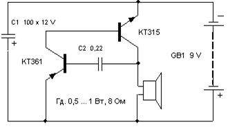
Transistors can be replaced with similar ones as in the previous circuit.
The total duration of the sound depends on capacity C1, and C2 determines the duration of pauses between “beats”. Sometimes, for a more believable sound, it is useful to select transistor VT1, since the operation of the simulator depends on its initial collector current and gain (h21e).
Engine sound simulator
They can, for example, voice a radio-controlled or other model of a mobile device.
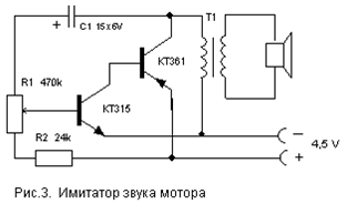
Options for replacing transistors and speakers - as in previous schemes. Transformer T1 is the output from any small-sized radio receiver (a speaker is also connected through it in the receivers).
There are many schemes for simulating the sounds of birdsong, animal voices, steam locomotive whistles, etc. The circuit proposed below is assembled on just one digital chip K176LA7 (K561 LA7, 564LA7) and allows you to simulate many different sounds depending on the value of the resistance connected to the input contacts X1.

It should be noted that the microcircuit here operates “without power,” that is, no voltage is supplied to its positive terminal (pin 14). Although in fact the microcircuit is still powered, this happens only when a resistance sensor is connected to the X1 contacts. Each of the eight inputs of the chip is connected to the internal power bus through diodes that protect against static electricity or incorrect connections. The microcircuit is powered through these internal diodes due to the presence of positive power feedback through the input resistor-sensor.
The circuit consists of two multivibrators. The first (on elements DD1.1, DD1.2) immediately begins to generate rectangular pulses with a frequency of 1 ... 3 Hz, and the second (DD1.3, DD1.4) comes into operation when the logical level " 1". It produces tone pulses with a frequency of 200 ... 2000 Hz. From the output of the second multivibrator, pulses are supplied to the power amplifier (transistor VT1) and a modulated sound is heard from the dynamic head.
If you now connect a variable resistor with a resistance of up to 100 kOhm to the input jacks X1, then feedback on nutrition and this transforms the monotonous intermittent sound. By moving the slider of this resistor and changing the resistance, you can achieve a sound reminiscent of the trill of a nightingale, the chirping of a sparrow, the quack of a duck, the croaking of a frog, etc.
Details
The transistor can be replaced with KT3107L, KT361G, but in this case you need to install R4 with a resistance of 3.3 kOhm, otherwise the sound volume will decrease. Capacitors and resistors - any type with ratings close to those indicated in the diagram. It must be borne in mind that the K176 series microcircuits of early releases do not have the above protective diodes and such copies will not work in this circuit! It’s easy to check the presence of internal diodes - just measure the resistance with a tester between pin 14 of the microcircuit (“+” power supply) and its input pins (or at least one of the inputs). As with diode testing, the resistance should be low in one direction and high in the other.
There is no need to use a power switch in this circuit, since in idle mode the device consumes a current of less than 1 µA, which is significantly less than even the self-discharge current of any battery!
Setup
A correctly assembled simulator does not require any adjustment. To change the tone of the sound, you can select capacitor C2 from 300 to 3000 pF and resistors R2, R3 from 50 to 470 kOhm.
Flashing light
The flashing frequency of the lamp can be adjusted by selecting elements R1, R2, C1. The lamp can be from a flashlight or a car 12 V. Depending on this, you need to select the supply voltage of the circuit (from 6 to 12 V) and the power of the switching transistor VT3.
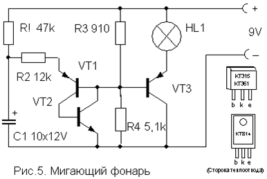
Transistors VT1, VT2 - any low-power corresponding structures (KT312, KT315, KT342, KT 503 (n-p-n) and KT361, KT645, KT502 (p-n-p), and VT3 - medium or high power (KT814, KT816, KT818).
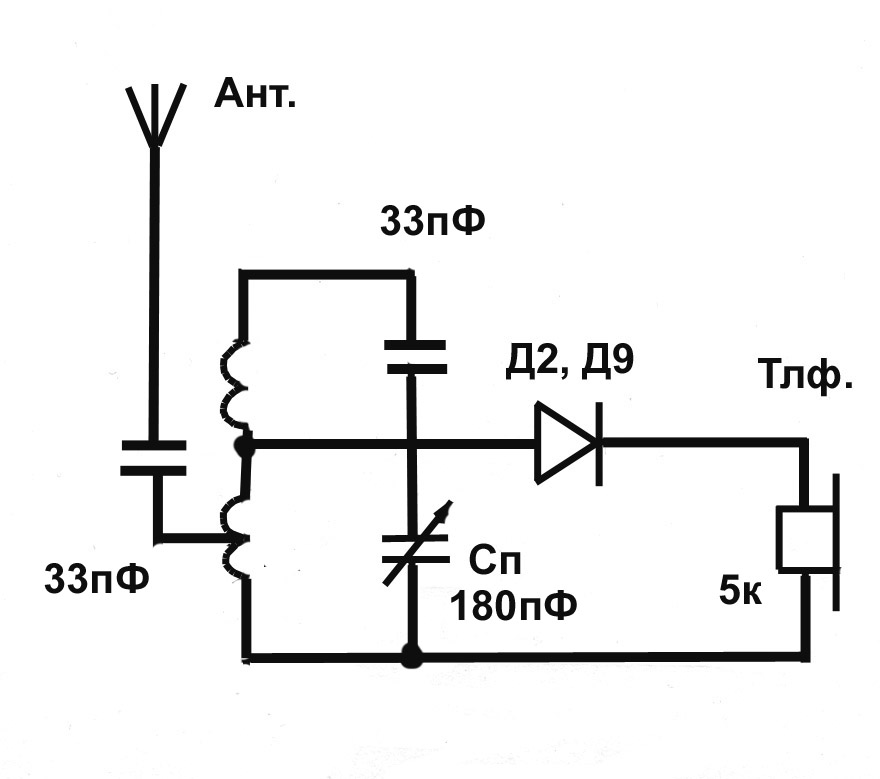
A simple device for listening to the sound of TV broadcasts on headphones. Does not require any power and allows you to move freely within the room.

Coil L1 is a “loop” of 5...6 turns of PEV (PEL)-0.3...0.5 mm wire, laid around the perimeter of the room. It is connected in parallel to the TV speaker via switch SA1 as shown in the figure. For normal operation of the device, the output power of the TV audio channel must be within 2...4 W, and the loop resistance must be 4...8 Ohms. The wire can be laid under the baseboard or in cable channel, in this case it is necessary to place it, if possible, no closer than 50 cm from the wires of the 220 V network to reduce alternating voltage interference.

The L2 coil is wound onto a frame made of thick cardboard or plastic in the form of a ring with a diameter of 15...18 cm, which serves as a headband. It contains 500...800 turns of PEV (PEL) wire 0.1...0.15 mm secured with glue or electrical tape. A miniature volume control R and an earphone (high-impedance, for example TON-2) are connected in series to the coil terminals.
Automatic light switch
This one differs from many circuits of similar machines in its extreme simplicity and reliability, and in detailed description doesn't need it. It allows you to turn on the lighting or any electrical appliance for a specified short time, and then automatically turns it off.

To turn on the load, just briefly press switch SA1 without latching. In this case, the capacitor manages to charge and opens the transistor, which controls the relay switching on. The turn-on time is determined by the capacitance of capacitor C and with the nominal value indicated in the diagram (4700 mF) it is about 4 minutes. An increase in the on-state time is achieved by connecting additional capacitors in parallel with C.
The transistor can be any n-p-n type of medium power or even low-power, such as KT315. This depends on the operating current of the relay used, which can also be any other with an operating voltage of 6-12 V and capable of switching the load of the power you need. Can also be used pnp transistors type, but you will need to change the polarity of the supply voltage and turn on capacitor C. Resistor R also affects the response time to a small extent and can be rated 15 ... 47 kOhm depending on the type of transistor.
List of radioelements
| Designation | Type | Denomination | Quantity | Note | Shop | My notepad | |
|---|---|---|---|---|---|---|---|
| Electronic duck | |||||||
| VT1, VT2 | Bipolar transistor | KT361B | 2 | MP39-MP42, KT209, KT502, KT814 | To notepad | ||
| HL1, HL2 | LED | AL307B | 2 | To notepad | |||
| C1 | 100uF 10V | 1 | To notepad | ||||
| C2 | Capacitor | 0.1 µF | 1 | To notepad | |||
| R1, R2 | Resistor | 100 kOhm | 2 | To notepad | |||
| R3 | Resistor | 620 Ohm | 1 | To notepad | |||
| BF1 | Acoustic emitter | TM2 | 1 | To notepad | |||
| SA1 | Reed switch | 1 | To notepad | ||||
| GB1 | Battery | 4.5-9V | 1 | To notepad | |||
| Simulator of the sound of a bouncing metal ball | |||||||
| Bipolar transistor | KT361B | 1 | To notepad | ||||
| Bipolar transistor | KT315B | 1 | To notepad | ||||
| C1 | Electrolytic capacitor | 100uF 12V | 1 | To notepad | |||
| C2 | Capacitor | 0.22 µF | 1 | To notepad | |||
| Dynamic head | GD 0.5...1W 8 Ohm | 1 | To notepad | ||||
| GB1 | Battery | 9 Volt | 1 | To notepad | |||
| Engine sound simulator | |||||||
| Bipolar transistor | KT315B | 1 | To notepad | ||||
| Bipolar transistor | KT361B | 1 | To notepad | ||||
| C1 | Electrolytic capacitor | 15uF 6V | 1 | To notepad | |||
| R1 | Variable resistor | 470 kOhm | 1 | To notepad | |||
| R2 | Resistor | 24 kOhm | 1 | To notepad | |||
| T1 | Transformer | 1 | From any small radio receiver | To notepad | |||
| Universal sound simulator | |||||||
| DD1 | Chip | K176LA7 | 1 | K561LA7, 564LA7 | To notepad | ||
| Bipolar transistor | KT3107K | 1 | KT3107L, KT361G | To notepad | |||
| C1 | Capacitor | 1 µF | 1 | To notepad | |||
| C2 | Capacitor | 1000 pF | 1 | To notepad | |||
| R1-R3 | Resistor | 330 kOhm | 1 | To notepad | |||
| R4 | Resistor | 10 kOhm | 1 | To notepad | |||
| Dynamic head | GD 0.1...0.5Watt 8 Ohm | 1 | To notepad | ||||
| GB1 | Battery | 4.5-9V | 1 | To notepad | |||
| Flashing light | |||||||
| VT1, VT2 | Bipolar transistor | ||||||