How to use a breadboard. Fast assembly of circuits on solderless breadboards Lightweight circuits on a breadboard
If in the first part of the article the emphasis was on a review of development boards and a description of their design, now we will consider some useful subtleties and nuances that you need to know when working with such development boards.
If the instructions for a solderless breadboard say that the diameter of the wire inserted into the contacts is 0.4 - 0.7 mm, then you should not try to insert leads of parts that are thicker than the specified value. This will cause the contacts to loosen and wear out. If there is a need to use such parts, then it is better to solder wires of the specified diameter to the thick leads, or simply wrap them around them. Naturally, the wire must be without insulation.
Solderless breadboards are sold in two configurations: with wires - jumpers and without them. In the first option, the board turns out to be somewhat more expensive, but it doesn’t matter at all if you managed to buy a separate board - you can always adapt something.
Switching wires, of course, are sold separately, but if there is no desire or opportunity to buy them, then the KSVV 4 * 0.4 wire used for installation is quite suitable.
Such a wire contains 4 insulated cores with a diameter of just 0.4 mm. The insulation from the wire is easily removed with side cutters or a knife, and the wires themselves do not have a varnish coating.
If it is necessary to prototype a complex device, it is better to assemble its individual functionally complete parts on separate small-sized breadboards, and then assemble the entire structure from the resulting components.
Sometimes it happens that one device has not yet been assembled, but for some reason you urgently need to assemble another, completely new one. And this is where it begins! It is necessary to disassemble the assembled, not yet debugged circuit, which then may have to be assembled again. But the only irreplaceable resource is the time that is lost on these meaningless assemblies and disassemblies. Therefore, it is better not to skimp, but to purchase several breadboards; things will go faster.
 We should not forget that development boards are designed for low-current equipment - and. Therefore, in no case is it permissible to supply them with mains voltage - 220 V. This can lead to overheating of the contacts and breakdown of the insulation, and what will happen after that is probably known to everyone.
But even in transistors and microcircuits, a short circuit can occur, which will cause overheating of these elements, lead to heating of the contacts and melting of the plastic base of the board. Therefore, when you turn on the circuit for the first time, it is advisable to measure the current consumption or at least check the temperature of all elements with your finger.
A general rule, not only for breadboards. First, components that are not affected by static electricity are installed: , and .
In addition to the parts, connecting wires are also installed on the breadboard. It is better to install the connecting wires with tweezers or small pliers. The same tools are used to dismantle the wires.
As in all such cases, check the board for correct installation and for absence of short circuits or loose contacts. Unused pins of microcircuits should not be left “hanging in the air”, but connected either to a common wire or to a power bus. Free inputs will simply lead to the appearance of interference at the outputs of such elements, which will spread throughout the entire circuit and its adjustment will become much more problematic.
 Probably, it should be noted here that breadboards have a large mounting capacity due to long connecting wires, as well as many contacts. Therefore, too high-frequency circuits on such boards will work poorly, or maybe not at all.
To avoid the influence of long conductors, it is advisable to shunt the power pins of the microcircuits with small-capacity ceramic capacitors, as is done on printed circuit boards.
When checking the correct installation, you can use “oak” TTL microcircuits, which are practically insensitive to static. You can, of course, do without them, but it’s not very convenient to push the multimeter probes into the holes on the board; it’s more convenient to touch the pins of the microcircuits. After completing the check and eliminating inaccuracies, the “training” microcircuits should be replaced with real ones.
When using CMOS microcircuits to protect against static, it is highly desirable to use antistatic grounding straps. If these are not available, then we can recommend using a wire wool for washing pans. This washcloth has the shape of a ring where you can stick your hand. Using a flexible wire through a resistor with a resistance of no more than 1 MOhm, connect to ground.
After checking the circuit, you can insert the mentioned CMOS chips into the board. When setting up the circuit, replacing parts, or making changes, it is better not to remove the protective antistatic wrist strap.
To design and debug prototypes of the most various devices Arduino uses breadboards (another name is solderless circuit boards and breadboards). They come in several varieties and differ in size and some other design features. Breadboard breadboards can help both budding engineers create simple circuits, and when prototyping complex devices. This article will tell you what a development board is and how to use this device.
Rarely what real project Arduino contains less than 5-10 elements connected to each other. Even in a simple, well-known beacon circuit, 2 elements are used, an LED and a resistor, which must somehow be connected to each other. And this is where the question arises of how to do this.
At the moment, there are the following main installation methods that are used in electronics and robotics at the prototyping stage:
- Soldering. To do this, use special boards with holes into which parts are inserted and connected to each other by soldering (using a soldering iron) and jumpers.
- Cheat. In this technology, the contact connections of the devices are combined with the breadboard by winding a clean wire to the pin contact.
The most modern version for creating prototypes is a solderless breadboard, which has undoubted advantages:
- Ability to carry out debugging work large number once changing the modification of circuits and methods of connecting devices;
- The ability to connect several boards into one large one, which allows you to work with more complex and large projects;
- Simplicity and speed of prototyping;
- Durability and reliability.
The English version of the name of a solderless breadboard is breadboard.
Development board diagram
To know how to use a development board, you need to understand the principle of its design.
The development board for solderless mounting has plastic base with many holes (standard distance between them is 2.54 mm). Inside the structure are rows of metal plates. Each plate has clips that are hidden in the plastic part of the unit.

The wires are inserted into these clips. When a conductor is connected to one of the individual holes, the contact is simultaneously connected to all other contacts of the separate row.
It is worth noting that one rail contains 5 clips. This is the general standard for all solderless boards. That is, up to five elements can be connected to each rail, and they will be interconnected.
It should be noted that although there are ten holes in each row, they are still divided into two isolated parts, five in each. Between them there is a rail without pins. This design is necessary to isolate the plates from each other, and allows you to simply connect chips made in DIP packages.

Some development boards also include two power lines on each side. Typically, the “red line” is used to supply “+” voltage, the “blue” line for “-”. Due to the presence of two power buses, the board can be supplied with two different levels voltage.
To make it easier to navigate, the breadboard also contains numerical and alphabetic symbols that can be used as a guide when creating, for example, wiring instructions.
Main types of development boards
Development boards differ in the number of pins located on the panel, the number of buses and configuration. There are also breadboards in which contact connections are made by soldering, but working with them is more difficult than with solderless devices.
Depending on the characteristics, the most common types are:
- For assembling large chips, solderless boards with 830 or 400 holes are mainly used. For connecting several components and supplying wires to the necessary points - 8, 10, 16 holes;
- With the presence of grooves for adhesion of boards, which allow the implementation of fairly large projects;
- With self-adhesive on the base for secure fastening to the device;
- With symbols printed on the board for connecting devices.
Depending on the cost and manufacturer, the package may also include additional accessories - jumper wires, various connectors. But the main quality criterion always remains the number of contact connectors and their technical characteristics.
How to use a development board
Using the breadboard is quite simple. When creating a circuit, insert into the holes on the plastic case necessary elements– capacitors, resistors, various indicators, LEDs, etc. The width of the connectors allows you to connect conductors with a cross-section from 0.4 to 0.7 mm to the contacts.
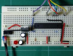
The simplest example of creating a circuit prototype using a breadboard would be the following implementation:

To assemble it you need to take:
- Breadboard;
- wires for connection;
- 1 LED;
- tact button;
- resistor with a nominal resistance of 330 Ohms;
- 9V Krona battery.
The plus of the battery is connected to the positive bus, and the minus to the negative. If the circuit is assembled correctly, then when you press the button the LED will light up.
Attention! Solderless breadboards are absolutely unacceptable to use with a voltage of 220V!
Breadboard breadboards are optimal for creating almost any digital circuits and are not intended for assembling analog circuits with high sensitivity to resistance values. In their practice, they are often used by both beginners who understand the basics of circuit design and experienced professionals due to the ease of installation and high quality connections of working contacts.
Breadboard design for simulation electronic circuits. (10+)
DIY breadboard
When developing various radio-electronic devices, I am often faced with the need to make a prototype. Of course, mathematical modeling is a great thing. But Firstly, not all schemes lend themselves mathematical modeling, A secondly, the mathematical model is not accurate enough. In general, after checking on a computer, it is imperative to assemble it live. At first I made a test circuit board, realizing that later I would have to throw it away. But then I started using a breadboard. I don’t like breadboards based on foil PCB at all. The reason is that they do not tolerate frequent resoldering well. Due to periodic heating, the conductors begin to lag behind. So a printed prototyping board is almost as disposable as a test board designed for a specific device.
Drawing of a homemade breadboard
As a result, I made a breadboard using my own technology, which I really liked. Now I use it everywhere. The board was made from non-foil PCB. You can take a foil one and remove the foil.
Unfortunately, errors are periodically found in articles; they are corrected, articles are supplemented, developed, and new ones are prepared. Subscribe to the news to stay informed.
If something is unclear, be sure to ask!
Ask a question. Discussion of the article.
More articles
DIY REA housing, REU. Homemade. Electronics. Radioelectron...
We will make a case for your electronic product...
Protection circuit against connection error of minus and plus (polarity reversal)....
Protection circuit against incorrect polarity of connection (reversal) of chargers...
PWM, PWM controller. Scheme. Chip. Operating principle. Description, conclusion...
PWM controller description of the operating principle....
Power powerful pulse transformer. Calculation. Calculate. Online. O...
Online calculation of power pulse transformer....
Sensor, indicator of combustion, flame, fire, torch. Ignition, fuse, spark...
Flame presence indicator combined with an igniter on one electrode...
Signals are mathematical (arithmetic) operations. Addition, summation...
Circuits for performing arithmetic operations on signals. Addition, subtraction...
Negative resistance, impedance. Scheme. Converter vs...
The concept of negative resistance. Circuits with negative resistance....
Schmitt trigger (Schmidt, Schmitt). Scheme. Electrical hysteresis. Calculate...
Schmitt trigger circuits and calculations. Hysteresis, response thresholds, input resistance...
For reliable assembly of devices, individual printed circuit boards. If you do them yourself, it will take a lot of time and force you to tinker with chemicals and a soldering iron. Individual boards with industrial installation to order are extremely expensive for small quantities.
For quick assembly electrical diagrams without soldering and without problems exists development board. It is also called a breadboard, breadboard or breadboard’om.
Operating principle
Under the layer of plastic are hidden copper plates-rails, laid out according to a simple principle:
Usage example
The same circuit on a breadboard can be assembled in many ways. Let's look at an example of one of the configurations for the following scheme:

On the breadboard, its physical embodiment can be done in this way:

What you should pay attention to:
The colors of the wires, of course, do not matter. However, it is good practice to use red wires for the power line and black or blue for the ground line.
We connected the power supply to the long side rails. This allows you not to pull a large number of wires to it itself from different parts of the circuit, and the task of replacing or moving it is greatly simplified
The position of the entire circuit on the breadboard is not that important. Important mutual position components relative to each other
Hi all. Today we will talk about solderless breadboard or breadboard, as the bourgeoisie call it. This board, so to speak, is included in the list of mandatory tools that an electronics engineer should have (whether he is a young brainiac who is just taking his first tentative steps or a seasoned brainiac who has seen life).
Knowledge of what types of breadboards there are, how and where such tools are used will help you during development and commissioning own projects various electronic homemade.
The first boards looked like this:

Attached to the base metal racks, onto which wires and contact terminals of the elements were subsequently fixed (simply wound).
It’s good that technological progress does not stand still, because thanks to its influence we can use such wonderful tools.

As opposed to a solderless breadboard, you can use these (they are much cheaper and are manufactured based on the required parameters).


However, when mounting on a solderless board, you will not need a soldering iron/solder. In addition, you will avoid the difficulties associated with soldering parts on the surface of the board.
The rule of good form, and common sense, has always been and remains the prototyping of electronic circuits. It is important to know how the device will behave under certain specific parameters before assembling the finished device.

In addition, using a solderless board, you can check the functionality of new components and radio components.
Let's look at the structure of a solderless board

Let's look at the board drawing. It consists of rows of metal plates (rails).
The rails, in turn, consist of clamps into which the “legs” of radio components are installed. All 5 holes in a row are connected together.


Now let's turn our attention to two vertical/horizontal stripes (depending on what position you look at), which are located separately (along the edges) - these are the power plates. All sockets of one long plate are connected to each other.
A central groove insulates the sides of the board. The width of this strip is fixed by the standard. It allows you to install DIP chips in such a way that each pin is installed in a separate rail and allows you to connect up to 4 external pins.

The boards are marked with alphabetic and digital sequences. These designations help you navigate when installing components in order to avoid erroneous connections (which could result in the circuit not working or failure of individual parts).
They also produce boards that are made on separate stands with special clamping terminals. They are used to connect the power supply to the board.

If you noticed, some boards have special grooves and protrusions (they are located on the sides). With their help, you can combine boards and create work surface any size.

Also, some boards have a self-adhesive backing on the back.
The figure shows a method of “powering” the board from Arduino.

If you come across a board with terminals for power supply, you need to connect them to the lines on the breadboard using conductors (jumpers). The terminals are not connected to any line. To connect a wire to a terminal, remove (unscrew) the plastic cap and place the end of the wire into the hole. Reinstall the cap. Typically two terminals are used: for power and for ground.
Now the only thing left to do is connect external source nutrition. This can be done with:
- jumpers;
- “crocodiles” or ordinary wires;

- power stabilizer modules that are produced for solderless boards.

Thank you for your attention. To be continued :)